












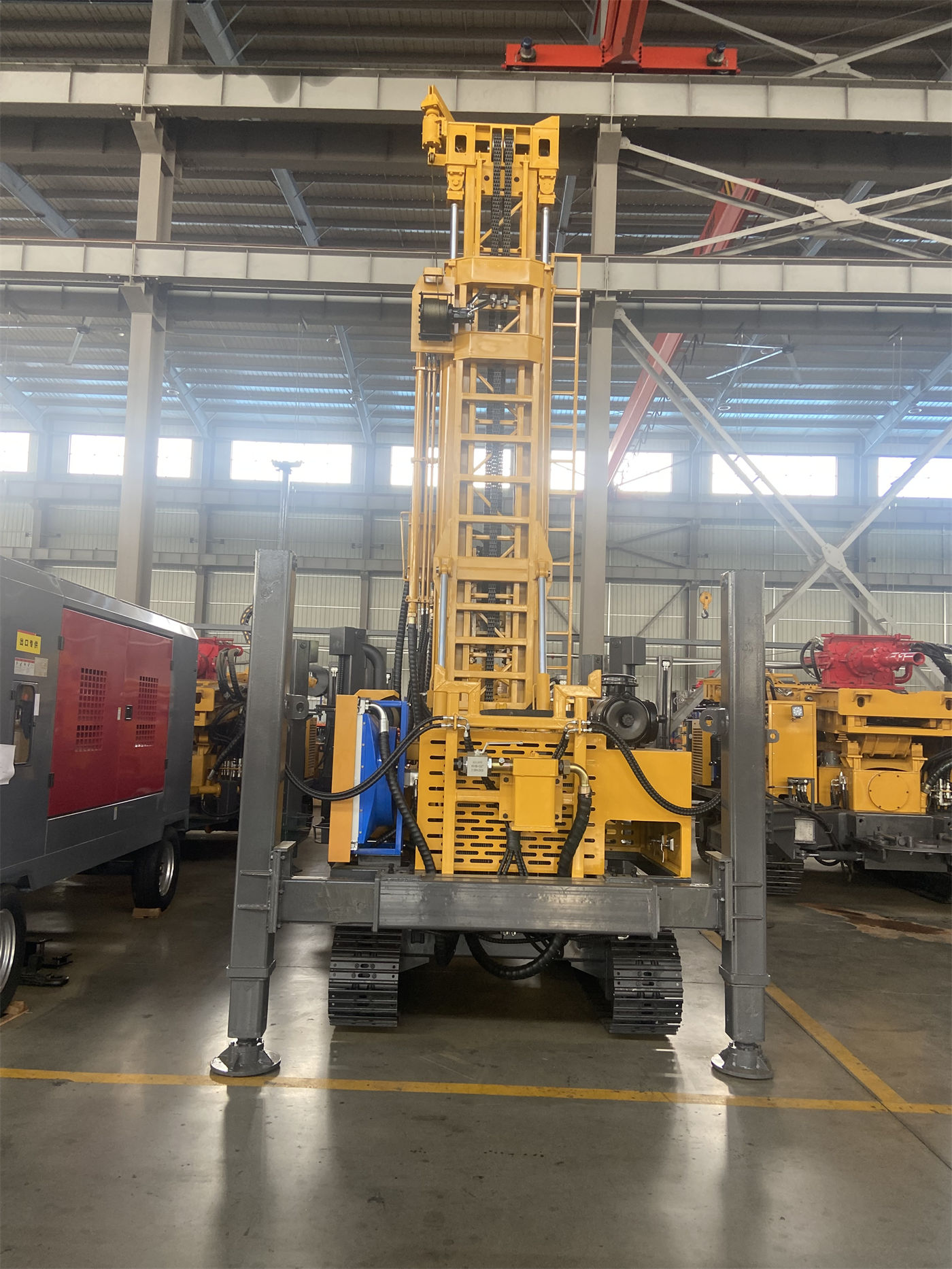
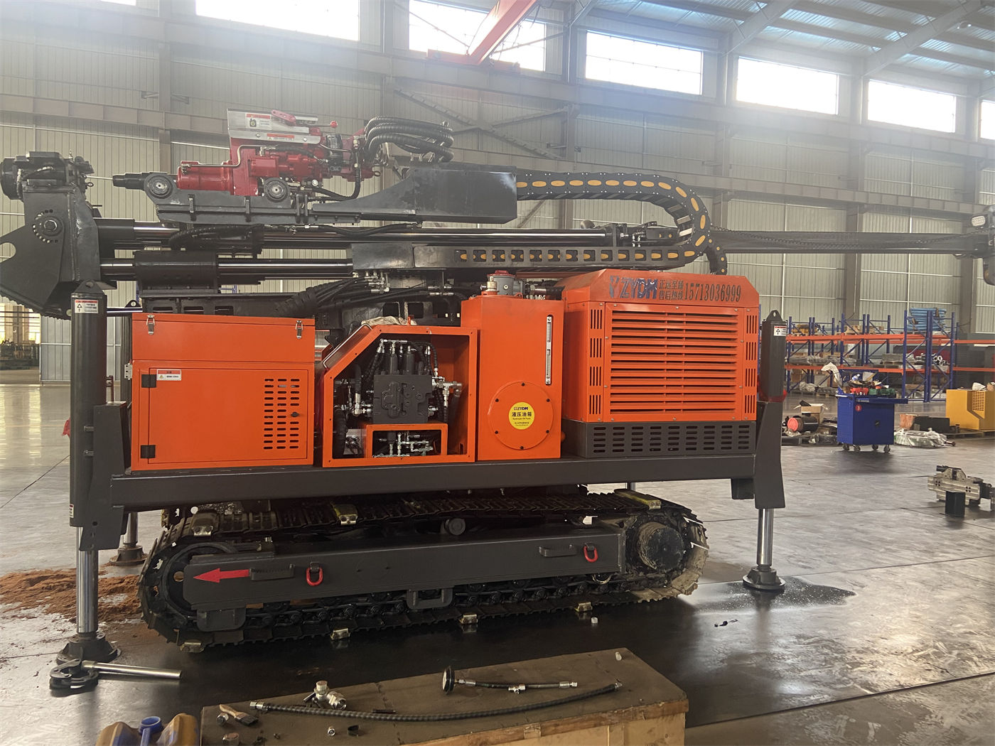
The WR1500S is a 1500 m-class crawler-mounted water well drilling rig with a telescopic mast. It supports 9.6 m drill pipe, an 80 T lifting force, and a rotary torque of 31,000/15,500 N·m. Deep-hole drill string management is not simply a matter of looking at the single figure of "1500 m drilling depth"; it requires verifying lifting force, torque, drill pipe specifications, hole diameter, downhole resistance, and construction organization together. The core conditions to confirm with the manufacturer before purchase include: whether the intended drill pipe diameter and length match the equipment, the drill string assembly and weight under each hole diameter, whether air compressor pressure and displacement can simultaneously meet the needs of the DTH hammer and cuttings removal, and whether the site and transportation can accommodate the 28 T complete machine and 9.6 m drill pipe.
Why deep-hole drill string management should come before price negotiation
As hole depth increases, the drill string's own weight, borehole wall friction, casing weight, and local sticking all rise. Lifting force, torque, axial pressure, and rotation speed together determine whether the equipment can complete normal tripping, drill string recovery, and some large-diameter casing operations. If these conditions are not clearly confirmed during procurement, problems such as "the depth rating is sufficient, but the actual assembly does not match" can easily arise after the equipment arrives on site.
It should be noted that the WR1500S maximum drilling depth of 1500 m is a nominal equipment capability value. Actual well depth should still be determined based on hydrogeology, hole diameter, drill pipe, air compressor, and well completion design, and it cannot be directly inferred from the nominal drilling depth that all projects can be completed in one pass.
First confirm the drill string assembly: 9.6 m drill pipe and 114/127 mm diameter
The WR1500S supports 9.6 m drill pipe, with recommended drill pipe diameters of 114/127 mm. Long drill pipe can reduce the number of make-up and break-out operations and auxiliary time for 1500 m-class deep holes, but it places higher demands on on-site operating space, drill pipe handling organization, and the load-bearing capacity of the drill pipe itself.
Recommended items to verify with the manufacturer before purchase
- The method for estimating total drill string weight when using 114 mm or 127 mm drill pipe at the planned well depth and under each hole diameter;
- The matching relationship between 9.6 m drill pipe and the telescopic mast, power head stroke, and make-up/break-out mechanism;
- The supply scope for drill pipe joint types, thread specifications, and matching elevators, slips, and other tools;
- 9.6 m drill pipe usually requires separate transportation, so whether the transportation and on-site storage plan needs to be confirmed together.
The materials do not provide a specific drilling depth allocation table for different drill pipe diameters, so it is not possible in this article to convert "how many meters can definitely be reached with 127 mm drill pipe." This data should be confirmed with the manufacturer as a dedicated topic in combination with the formation and well completion design.
What an 80 T lifting force and 16 T axial pressure can cover
The WR1500S has an 80 T lifting force, 16 T axial pressure, 28 m/min fast lifting speed, and 44 m/min fast feed speed. Lifting force mainly affects the margin for tripping, drill string recovery, and some large-diameter casing operations; axial pressure affects feed capability. The two should be viewed separately, and a "large lifting force" should not be equated with "being able to forcibly pull out all downhole resistance."
The materials clearly indicate that when abnormal resistance occurs, the priority should still be to clean the hole, lift slowly, and judge the downhole condition, rather than directly pulling hard at maximum lifting force. During procurement, confirm:
- The definition of rated working conditions corresponding to the 80 T lifting force and the safe use boundary;
- The adjustable range and feed matching of the 16 T axial pressure under different hole diameters and rock formations;
- Which tools can be handled by the 5 T large auxiliary winch and 2.5 T small auxiliary winch, and how the rated lifting load and safe distance are defined.
How to verify the 31,000/15,500 N·m dual-condition torque
The WR1500S has a maximum rotary torque of 31,000/15,500 N·m and a maximum rotation speed of 70/140 r/min. Low speed and high torque are more suitable for large-diameter, hard rock, and high-friction conditions, while higher rotation speed is suitable for stable hole sections with relatively low resistance. In 1500 m-class deep holes, the torque gear should be adjusted dynamically based on drill string load, cuttings return, and drill tool condition.
During procurement, the manufacturer can be asked to explain: within the 105–1000 mm hole diameter range, which hole diameter intervals rely more on the 31,000 N·m gear, and which stable hole sections are suitable for 15,500 N·m with 140 r/min. The materials do not provide recommended torque values for each hole diameter, and this article does not make calculations.
Associated requirements of 105–1000 mm hole diameter for the drill string and supporting equipment
The WR1500S has a drilling diameter of 105–1000 mm, covering conventional deep water wells, large-diameter groundwater wells, mine dewatering, and some large engineering holes. The larger the hole diameter, the higher the requirements for the air compressor, drill tools, casing, rotary torque, and lifting capacity.
Before purchase, confirm which interval the project's target hole diameter falls into, and simultaneously verify: casing specifications and running method, bit and DTH hammer matching, and whether the cuttings removal channel is sufficient. If the hole diameter approaches 1000 mm, it is not enough to look only at the drilling rig's own parameters; air compressor displacement and the drill string assembly must also be included in the verification.
Matching conditions for air compressor pressure and displacement
When using DTH hammer drilling, the WR1500S recommends a working air pressure of 1.65–8 MPa and an air consumption of 16–120 m³/min. 1500 m-class deep holes and large-diameter hard rock projects have high requirements for air compressor displacement. Pressure and displacement must simultaneously meet the needs of the DTH hammer and bottom-hole cuttings removal; otherwise, insufficient impact, difficult cuttings removal, and bottom-hole cuttings accumulation can easily occur.
During procurement, confirm with the manufacturer: the air pressure and air consumption corresponding to the intended DTH hammer model, the air compressor configuration plan, high-pressure air hose specifications, and whether pipeline pressure loss under deep-hole conditions requires additional calculation. The materials do not provide pressure loss data for different hole depths; this part belongs to on-site supporting design.
Pipe make-up and break-out and on-site organization
9.6 m drill pipe reduces the frequency of pipe make-up, but it also means each pipe is longer and heavier, placing higher demands on handling and storage. The WR1500S is equipped with dual auxiliary winches, which can be used for handling DTH hammers, drill pipe, casing tools, and general accessories, helping to reduce manual handling intensity.
- Confirm whether the drill pipe handling route, storage rack, and lifting equipment match the 9.6 m drill pipe length;
- Confirm the relationship between the make-up/break-out operating space and the working height of the telescopic mast;
- Confirm whether the site has reserved areas for the air compressor, mud system, drill tools, and materials.
Judging downhole anomalies and deep-hole risks
The construction and maintenance tips provided in the materials include: during deep-hole construction, continuously record torque, air pressure, cuttings return, water return, and pull-out resistance; when trend anomalies are found, stop the machine promptly for analysis. After entering the main aquifer, water inflow will change downhole cuttings removal and the working state of the DTH hammer. The depth of the main water-producing layer should be recorded, and air supply, hole cleaning, and casing methods should be adjusted according to water volume.
When encountering weathered rock, fractures, or fault fracture zones, reduce feed speed, strengthen hole cleaning, and use casing, foam, or other hole stabilization measures according to actual conditions; if cuttings return continues to decrease or pull-out resistance increases significantly, stop drilling promptly for inspection. Once the upper overburden experiences diameter reduction or collapse, it will directly affect subsequent deep construction, so establishing a stable hole body should be prioritized during the opening stage.
Transportation conditions for the 28 T complete machine and 9.6 m drill pipe
The WR1500S complete machine weighs about 28 T, has overall dimensions of about 11.5 × 2.6 × 3.5 m, a travel speed of 3.5 km/h, a maximum climbing angle of 21°, and a hydraulic outrigger stroke of 1.7 m. For cross-regional transportation, confirm in advance the flatbed truck load capacity, road height limits, bridge load capacity, and turning space.
| Confirmation item | Basis in the materials |
|---|---|
| Complete machine transportation | About 28 T, 11.5 × 2.6 × 3.5 m |
| Drill pipe transportation | 9.6 m drill pipe usually requires separate transportation |
| Site requirements | Reserve areas for air compressor, mud system, drill tools, and materials |
Applicable working conditions and items requiring separate confirmation
The WR1500S is aimed at large deep-hole projects such as deep water wells, mining water supply, industrial water, dewatering, and geothermal surveys. In geothermal survey projects, in addition to drilling depth, formation temperature, circulation medium, casing material, and borehole wall stability must also be considered; when formal geothermal development wells are involved, drill tools and the well completion system should be configured according to a dedicated design.
This article is based on the site's product materials and does not involve specific customer cases, transaction records, or measured data. Actual drilling efficiency, drilling depth, and well completion results are subject to on-site conditions; the reference drilling efficiency of 10–35 m/h is within the range indicated in the materials and cannot be directly used as a project schedule commitment. Before purchase, it is recommended to include the above drill string management conditions item by item in a technical confirmation checklist and have the manufacturer reply in writing in combination with the project's hydrogeological data.