












The WR200SE is positioned as a cost-effective 200 m-class telescopic mast crawler water well drilling rig, equipped with a Yuchai 58 kW diesel engine, a drilling diameter of 140–254 mm, a single feed length of 3.3 m, a rotary torque of 3400–4700 N·m, and a lifting force of 13 T. It is aimed at medium-to-shallow water well projects such as rural water supply, farmland irrigation, livestock water, construction water, and small mining area water wells. The so-called "configuration limits" mainly lie not in the nominal drilling depth of 200 m, but in three areas: first, whether this depth can reach the aquifer position under your hydrogeological conditions; second, whether the 140–254 mm hole diameter, 1.5/2.0/3.0 m drill pipes, and 13 T lifting force can match your well completion structure; third, whether the air compressor can supply the required 1.7–2.5 MPa working air pressure and 17–31 m³/min air consumption. The following sections are based on verified parameters, and parts without supporting data only indicate directions that need confirmation.
Limit One: For rural water supply and farmland irrigation, well depth is determined by the aquifer, not by the equipment's upper limit
The WR200SE has a maximum drilling depth of 200 m, covering a larger depth range than 120 m-class small rigs, making it suitable for rural areas with relatively deep groundwater levels, farmland irrigation areas, and hilly terrain. However, the materials also state the premise: actual completed well depth still needs to be determined in combination with local hydrogeology, aquifer position, hole diameter, drilling tools, and construction technology. In other words, 200 m is the equipment capability limit, not the project well depth target.
For villages with insufficient domestic water and centralized water supply, the equipment can drill household wells, village domestic water wells, and small public water intake wells; for farmland irrigation wells, orchard wells, greenhouse water supply, and nursery irrigation, the matching of well diameter, filter pipe, and pump type under long-term pumping conditions must be considered. The materials recommend determining well diameter, filter pipe, and pump type based on expected water yield before construction, rather than simply pursuing a larger hole diameter. The larger the hole diameter, the higher the air volume, rotation, and cuttings discharge burden per unit footage, which must be calculated together with the air compressor when selecting the upper limit diameter of 254 mm.
Limit Two: Soil, sand and gravel, and fractured zones cannot be handled by the DTH hammer alone
A common problem in water well projects is not that the bottom hard rock cannot be drilled, but that the upper hole section fails first. According to the materials, in the upper soil layer, clay, sand layer, or sand and gravel layer, directly using a DTH hammer is not necessarily the best solution; loose overburden is prone to hole collapse, drill pipe burial, and hole diameter enlargement. The upper hole section should be treated first with casing, mud, or other hole stabilization methods before entering stable rock formations to continue drilling.
After entering relatively intact rock formations such as limestone, sandstone, and granite, suitable DTH hammers and bits can be used for pneumatic drilling, with focus on controlling air volume, rotation, and feed coordination. Fractured rock and fracture-developed formations may cause air leakage, block falling, and drill pipe sticking. During construction, excessively fast feed should be reduced, continuous hole cleaning should be maintained, and changes in air pressure and cuttings discharge in the hole should be observed; if the fractured zone is thick, casing advancement or casing methods can be considered. Weathered rock formations usually have faster footage, but hole wall stability may be poor. Whether to follow up with casing should be determined based on block falling and hole shrinkage. After drilling into the aquifer, water inflow will change the cuttings discharge state in the hole and the working conditions of the DTH hammer. Air supply and hole cleaning methods need to be adjusted, and the aquifer depth should be recorded. Before well completion, the well pipe, filter pipe, and water stop structure should be reasonably arranged.
Therefore, before purchase, what should be confirmed is: in the project formation profile, how thick the soil layer, sand and gravel layer, and fractured zone are, and whether casing, mud, or other hole stabilization methods are prepared, rather than only asking whether the equipment can drill 200 m.
Limit Three: The air compressor must be matched together with hole diameter, hole depth, DTH hammer, and altitude
The WR200SE itself only provides a matching range: reference working air pressure 1.7–2.5 MPa, air consumption 17–31 m³/min, and it clearly states that the matching description should select the air compressor according to hole diameter, DTH hammer specifications, target hole depth, altitude, and rock hardness. When the hole diameter increases, the rock formation becomes harder, or the altitude rises, a more sufficient displacement is usually required; insufficient air compressor matching will directly affect impact frequency, cuttings discharge, and drilling efficiency.
| Parameter | Verified Value |
|---|---|
| Maximum drilling depth | 200 m |
| Drilling diameter | 140–254 mm |
| Drill pipe diameter | 76 / 89 mm |
| Drill pipe length | 1.5 / 2.0 / 3.0 m |
| Single feed length | 3.3 m |
| Lifting force | 13 T |
| Fast lifting speed / fast feed speed | 30 m/min / 60 m/min |
| Rotary torque / rotary speed | 3400–4700 N·m / 45–70 r/min |
| Engine | Yuchai, 58 kW |
| Working air pressure / air consumption | 1.7–2.5 MPa / 17–31 m³/min |
| Overall weight / dimensions | Approx. 4.7 T / Approx. 3950 × 1750 × 2250 mm |
| Travel speed / maximum gradeability | 2.5 km/h / 30° |
| Reference drilling efficiency | 10–35 m/h |
The 1.7–2.5 MPa and 17–31 m³/min in the table are the equipment's matching reference ranges, not universal values that can be arbitrarily applied to an air compressor. During purchase, the target hole diameter, target hole depth, intended DTH hammer model, project altitude, and main rock hardness should be provided to the manufacturer for verification to confirm what displacement is required under which combination of hole diameter and depth. The materials do not provide specific air compressor models and matching prices; this part needs separate confirmation.
Mast and drill pipe: What does a 3.3 m single feed mean for rural water well projects?
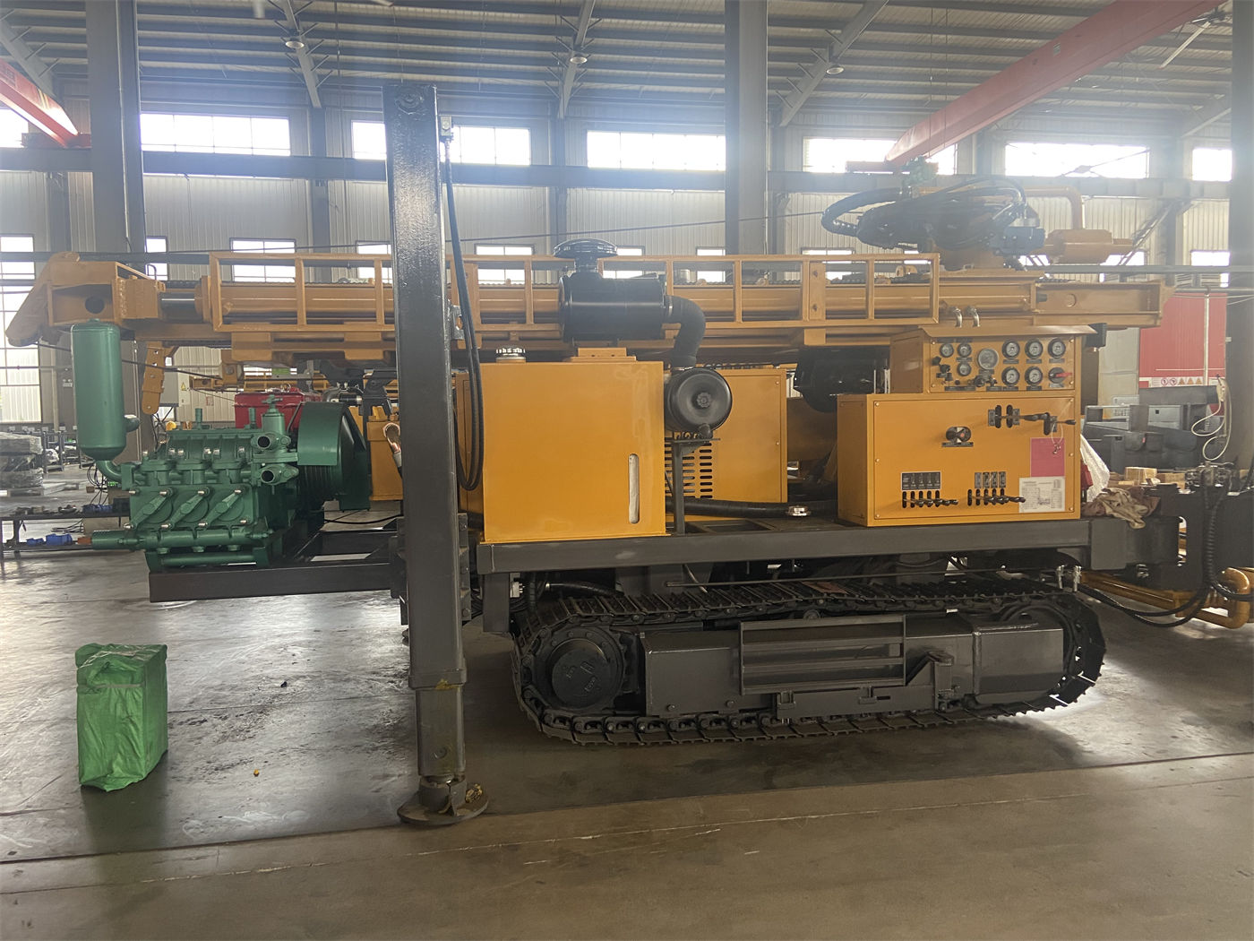
This model uses a telescopic mast with a single feed length of 3.3 m and can be equipped with 1.5 m, 2.0 m, and 3.0 m drill pipes. The telescopic structure is more flexible than a fixed long mast in terms of transportation and site adaptability, while in normal working conditions it can provide working space for drill pipe handling and continuous drilling. The fast lifting speed of 30 m/min and fast feed speed of 60 m/min are used for power head movement and drill pipe operations in non-drilling states, with the purpose of reducing auxiliary time such as loading and unloading drill pipes and lifting and lowering drilling tools; actual rock footage speed still depends on lithology, DTH hammer, bit, and air compressor capability, and the reference efficiency of 10–35 m/h cannot be used as a construction period commitment.
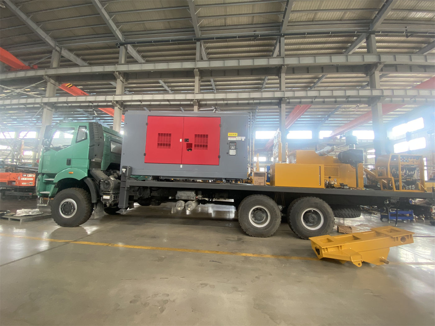
The 13 T lifting force is used for normal tripping, drill pipe handling, and some casing operations. When encountering drill pipe sticking, hole wall shrinkage, or abnormal water return, the handling direction given in the materials is to first judge the formation and downhole conditions, then solve the problem through hole cleaning, pulling out the drill pipe for inspection, or casing treatment, rather than simply relying on large lifting force to pull the drilling tools forcefully. This is especially important for rural water well teams, because such projects often lack heavy-duty handling equipment.
Chassis and site conditions: Travel limits of the crawler rig
The overall weight is about 4.7 T, and the dimensions are about 3950 × 1750 × 2250 mm, placing it in the range of small-to-medium crawler water well drilling rigs. Compared with large rigs above 500 m, it is easier to arrange transport vehicles and is also suitable for water well construction teams with many hole positions and frequent site transfers. The crawler chassis travel speed is about 2.5 km/h, and the maximum gradeability reference is 30°, suitable for rural roads, farmland, gravel sites, and mildly uneven ground; when moving on slopes, the center of gravity should be lowered, the mast retracted, and ground adhesion conditions confirmed. Actual safe gradeability should be judged according to site conditions.
The 1.4 m high outrigger stroke can be used for support and leveling on uneven sites. Before drilling begins, the chassis and outriggers should be ensured to bear force stably, and pads should be added if necessary to avoid tower tilting and hole position deviation caused by sinking on soft ground. For farmland and orchard projects, the access road width, bridge and culvert load-bearing capacity, and travel conditions of field ridges and irrigation ditches are recommended to be verified as separate matters before purchase; the materials do not provide these specific limit values.
Before purchase, it is recommended to check these five items one by one
- Hydrogeological data: local groundwater level, main aquifer depth and thickness, based on which to judge whether 200 m-class equipment is sufficient, rather than directly quoting the project well depth as 200 m.
- Well structure and hole diameter: whether the target well diameter falls within 140–254 mm, whether the well pipe, filter pipe, and pump type match the hole diameter, and whether there will be a situation where "the hole diameter is selected too large and the air compressor cannot keep up."
- Formation combination and hole stabilization plan: how thick the upper soil layer, sand and gravel layer, and fractured zone are, whether casing, mud, or other hole stabilization measures are needed, and whether casing advancement tools are within the purchase scope.
- Air compressor matching: provide hole diameter, hole depth, DTH hammer specifications, altitude, and rock hardness to the manufacturer, confirm the required air pressure and displacement, and clarify whether the air compressor, air pipe, oil mist lubricator, and foam equipment are within the purchase scope.
- Accessories and maintenance: the specification combination of 76 mm or 89 mm drill pipes, DTH hammer, bits, and casing tools, as well as the preparation of wearing drilling tools and daily inspection items (hydraulic lines, rotary head, winch, crawler, mast, drill pipe connections, air compressor and high-pressure air pipe joints, and safety devices).
The "E" in WR200SE indicates a cost-effective configuration, with the focus on balancing equipment price, maintenance difficulty, and daily use cost while meeting the requirements of conventional 200 m-class water well construction. This positioning is of reference significance to regional drilling teams, farmland water conservancy construction teams, and customers who have just entered the water well drilling rig business, but whether it is suitable for a specific rural water supply or irrigation project still depends on the above working condition data. Items not provided in the materials include: specific air compressor models and prices, actual well completion efficiency in different formations, configuration lists of casing and casing advancement tools, transport vehicle requirements, and well completion case data under various geological conditions. These all need to be confirmed item by item with the manufacturer during the inquiry and contract stages, and it is not recommended to make decisions based solely on nominal drilling depth and hole diameter.