












The WR400S's 6 m casing direct operation capability and telescopic mast structure affect two things: first, the procedure arrangement for casing running and joint make-up during the well completion stage; second, the way the equipment is loaded and transferred between multiple hole positions and multiple job sites. Before purchase, these two points need to be checked together with the project's hydrogeological conditions, casing specifications, and transfer distance, rather than just looking at the 400 m drilling depth figure.
Verified Core Parameters of the WR400S
The following parameters come from this site's product information. For procurement, the manufacturer's final confirmed technical documents shall prevail.
| Item | Data Value |
|---|---|
| Model | WR400S (S stands for telescopic mast) |
| Maximum drilling depth | 400 m |
| Hole diameter | 105–325 mm |
| Drill pipe and casing operation capability | Supports 6 m drill pipe and 6 m casing direct operation; recommended drill pipe diameter 89 / 102 mm |
| Engine | 92 kW Yuchai |
| Lifting force | 22 T |
| Axial pressure | 4 T |
| Rotary system | Maximum torque 8000 / 4000 N·m, corresponding to maximum rotation speed 75 / 150 r/min |
| Fast lift / fast feed | 29 m/min / 56 m/min |
| Working air pressure (DTH hammer) | 1.2–3.5 MPa, air consumption 16–55 m³/min |
| Crawler travel speed | Approximately 2.5 km/h, maximum climbing angle reference 21° |
| Hydraulic outrigger stroke | 1.6 m |
| Auxiliary winch lifting force | 1.5 T |
| Overall weight | Approximately 9.8 T |
| Dimensions (transport configuration) | Approximately 6.26 × 1.85 × 2.43 m |
| Optional accessories | Mud pump, centrifugal pump, generator, foam pump |
What 6 m Casing Direct Operation Means for Well Completion
Reducing the Number of Make-and-Break Operations During Casing Running
Casing serves the functions of wall protection, layer isolation, and water shutoff in well completion. The information shows that the WR400S can support 6 m casing direct operation, which means a longer single casing length can be run into the hole, and the number of connections during casing running is correspondingly reduced. The direct change from fewer connections is a decrease in wellhead operation time and manual coordination frequency, while also reducing the alignment and sealing issues that may arise from each connection.
It should be noted that 6 m is the casing operation length the equipment can support, which does not mean that 6 m casing can be used for any well diameter and well depth. Casing diameter, wall thickness, connection method, and casing running resistance still need to be judged separately according to the target well diameter (equipment hole diameter range 105–325 mm) and borehole wall stability.
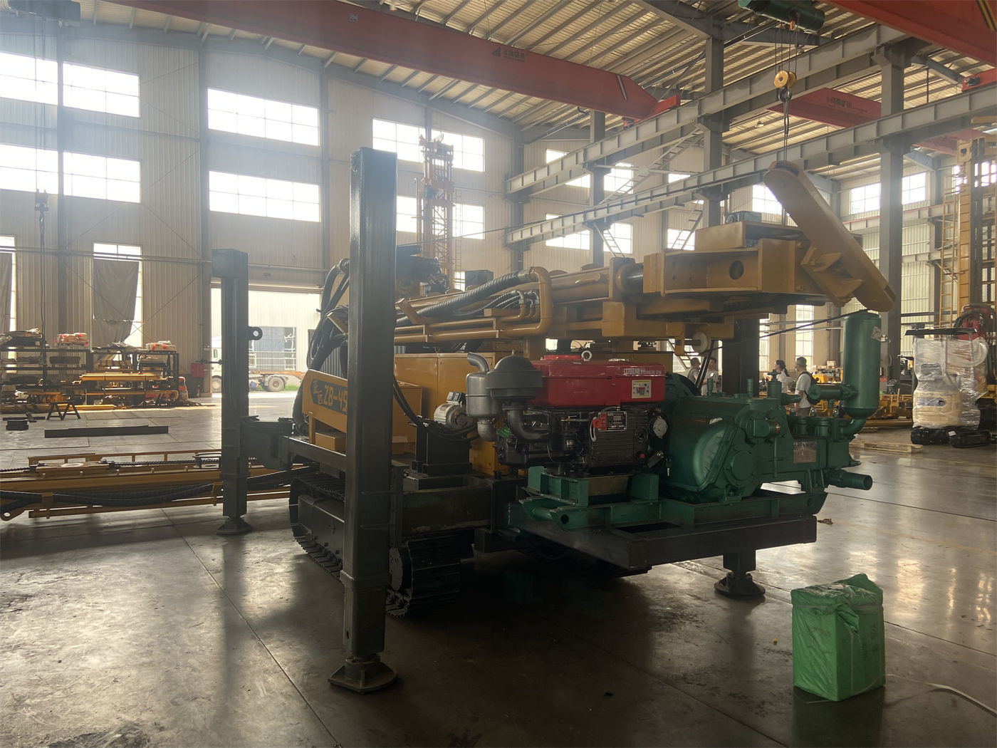
Arrangement Space for Casing Running and Water Shutoff Procedures
In well completion, the casing running depth, screen position, and water shutoff section layout depend on the aquifer depth and aquiclude distribution. What 6 m casing direct operation brings is margin in procedure organization: if the positions of the water shutoff section or screen section are close to a multiple of 6 m, the on-site work of cutting and connecting casing will be less. However, screen open area ratio, wire wrapping specifications, and water shutoff materials fall within the scope of well completion design, and the information does not provide corresponding values. During procurement, these should be confirmed separately with the manufacturer and the well completion designer.
Interface with the Drilling Procedure
The 6 m drill pipe and 6 m casing use the same length system, making the tool switch between drilling and casing running more consistent. The information mentions that long drill pipes can significantly reduce the number of pipe connections in 300–400 m class water wells, lowering auxiliary time and manual handling frequency. Buyers can use this to calculate the time saved per hole from fewer make-and-break operations, but the actual savings depend on the formation, hole diameter, and crew organization, and fixed values should not be directly applied.
What the Telescopic Mast Means for Site Transfer Planning
Switching Between Transport and Working Configurations
The WR400S's telescopic mast can shorten the overall machine profile in transport configuration, and then extend to working configuration after arriving at the hole position, continuing to support 6 m drill pipe or 6 m casing construction. The information gives transport configuration dimensions of approximately 6.26 × 1.85 × 2.43 m and an overall weight of approximately 9.8 T. For crews that need to load frequently, this structure mainly affects the difficulty of loading, road passage, and site turning.
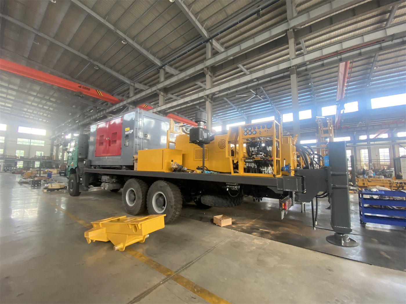
Crawler Chassis and Movement Between Hole Positions
The equipment uses a crawler chassis, with a travel speed of approximately 2.5 km/h and a maximum climbing angle reference of 21°. The crawler structure is suitable for rural roads, gravel ground, and generally uneven sites. It can move by itself between multiple hole positions within the same job site, but still needs to be loaded and transported between job sites. The information specifically notes that before transfer, the mast should be in a safe transport configuration, and ground bearing capacity, slope, and wet slippery conditions should be assessed. Whether it is suitable for a specific road condition is not sufficiently covered by the information and needs to be confirmed based on local road and site conditions.
Hydraulic Outriggers and Positioning and Leveling
The hydraulic outrigger stroke is 1.6 m, used for equipment leveling and stable support. The construction cycle for a single 400 m class water well hole is relatively long, and the equipment's level state will affect hole deviation and mast stress. The information notes that on soft ground, pads should be used to ensure even outrigger loading and avoid settlement during construction. This is especially important to allow time for in the procedure during continuous transfer between multiple hole positions.
Supporting Equipment and Working Condition Items to Verify with the Manufacturer Before Purchase
- Casing specifications and connection method: The information states support for 6 m casing direct operation, but does not list applicable casing diameter, wall thickness, and connection type, which need to be confirmed according to the target well diameter.
- Air compressor matching: When using a DTH hammer, the recommended working pressure is 1.2–3.5 MPa and air consumption is 16–55 m³/min. The air compressor must satisfy both pressure and displacement; insufficient displacement in large-diameter, hard rock, and high-altitude environments will affect impact and cuttings removal.
- Mud system options: The information shows that the WR400S supports mud drilling and can be optionally equipped with a mud pump and centrifugal pump. Loose overburden such as soil, clay, and sand layers requires mud for wall protection and cuttings carrying, and whether to equip it should be decided according to the thickness of the upper overburden.
- Basis for dual-mode switching: The rotary system is dual-mode at 8000 / 4000 N·m, corresponding to 75 / 150 r/min. The information notes that switching should be based on drilling tools, rock formation, and cuttings return conditions, rather than maintaining a single mode for a long time. Which gear to use under which hole diameter and rock formation needs to be determined in combination with bit type and on-site feedback.
- Lifting force verification: Lifting force is 22 T and axial pressure is 4 T. In 400 m class drilling, the weight of drill pipes, borehole wall friction, and casing weight will gradually increase. During procurement, a calculation should be made according to the planned maximum well depth, drilling tool assembly, and casing weight to see whether there is margin.
- Well completion design parameters: Well casing, screen, water shutoff section, and pump configuration fall within well completion design. The information does not provide corresponding data and they need to be confirmed separately.
- Telescopic mast maintenance parts: The information notes that in addition to routine inspection of the engine, hydraulic system, crawler, outriggers, and drilling tools, special attention should be paid to inspecting the telescopic mast guide rails, hydraulic cylinders, pins, and locking structures. During procurement, the spare parts supply for these components can also be confirmed.
Applicable Scenarios and Judgment Boundaries
The information lists the WR400S's applicable directions as farmland irrigation, rural water supply, aquaculture, and industrial construction water wells. The 400 m drilling depth and 105–325 mm hole diameter cover part of the medium-to-deep groundwater development needs. For areas with unstable shallow groundwater, relatively deep groundwater levels, or the need for greater water exploration margin, it has a wider construction range than small shallow well drilling rigs.
However, the actual well completion depth should still be determined according to hydrogeological conditions. The information does not provide formation cases for specific regions, well completion success rates, or single-hole construction cycle data, nor does it include any customer usage records. When deciding whether the WR400S matches a project, the buyer needs to organize the target well depth, target well diameter, upper overburden thickness, main rock formation type, and planned transfer distance into a working condition checklist, and then verify them item by item with the manufacturer, rather than making a judgment based only on drilling depth.