












The WR500S has nominal specifications of a maximum drilling depth of 500 m, drilling diameters of 105–400 mm, 30 T lifting capacity, 11000/5500 N·m dual-mode rotary torque, 6 m drill pipes, and a 110 kW Yuchai engine. When purchasing, the question is not whether these figures are "large enough," but whether they are sufficient under actual borehole diameters, well depths, drill string configurations, and rock formation techniques. This article explains the operating variables corresponding to each parameter and the information that must be confirmed with the manufacturer, following the order of verification.
First Determine the Borehole Diameter and Well Depth Combination, Then Examine Torque and Lifting Capacity
The WR500S has a drilling diameter range of 105–400 mm and a maximum drilling depth of 500 m. These two upper limits cannot both be satisfied in any arbitrary combination: the larger the borehole diameter, the larger the annular cuttings return area, and the greater the rotary resistance, required air volume, or mud displacement. The greater the well depth, the more the drill pipe string's own weight, borehole wall friction, and tripping frequency increase. Before purchasing, the project should be written as several combinations of "borehole diameter + design well depth + main rock formation," rather than just a single 500 m figure.
- Rural deep water wells and small community water supply typically involve greater well depths but relatively limited completed well diameters, requiring focused verification of drill pipe self-weight and lifting margin in deep-hole sections.
- If farmland irrigation or mining area water supply requires larger water output, the borehole diameter and well casing specifications will increase the demands on rotary torque and cuttings return capacity.
- When the proportion of hard rock in mining areas is high, the degree of rock integrity, DTH hammer specifications, and air compressor displacement should all be included in the verification.
Applicable Boundaries of the 11000/5500 N·m Dual-Mode Torque
The WR500S rotary system has a maximum torque of 11000/5500 N·m, corresponding to maximum rotary speeds of 75/150 r/min. The low-speed, high-torque mode is used for large borehole diameters, hard rock, and higher loads; the higher-speed mode is used for drilling stages with relatively lower resistance. Items to confirm before purchasing include:
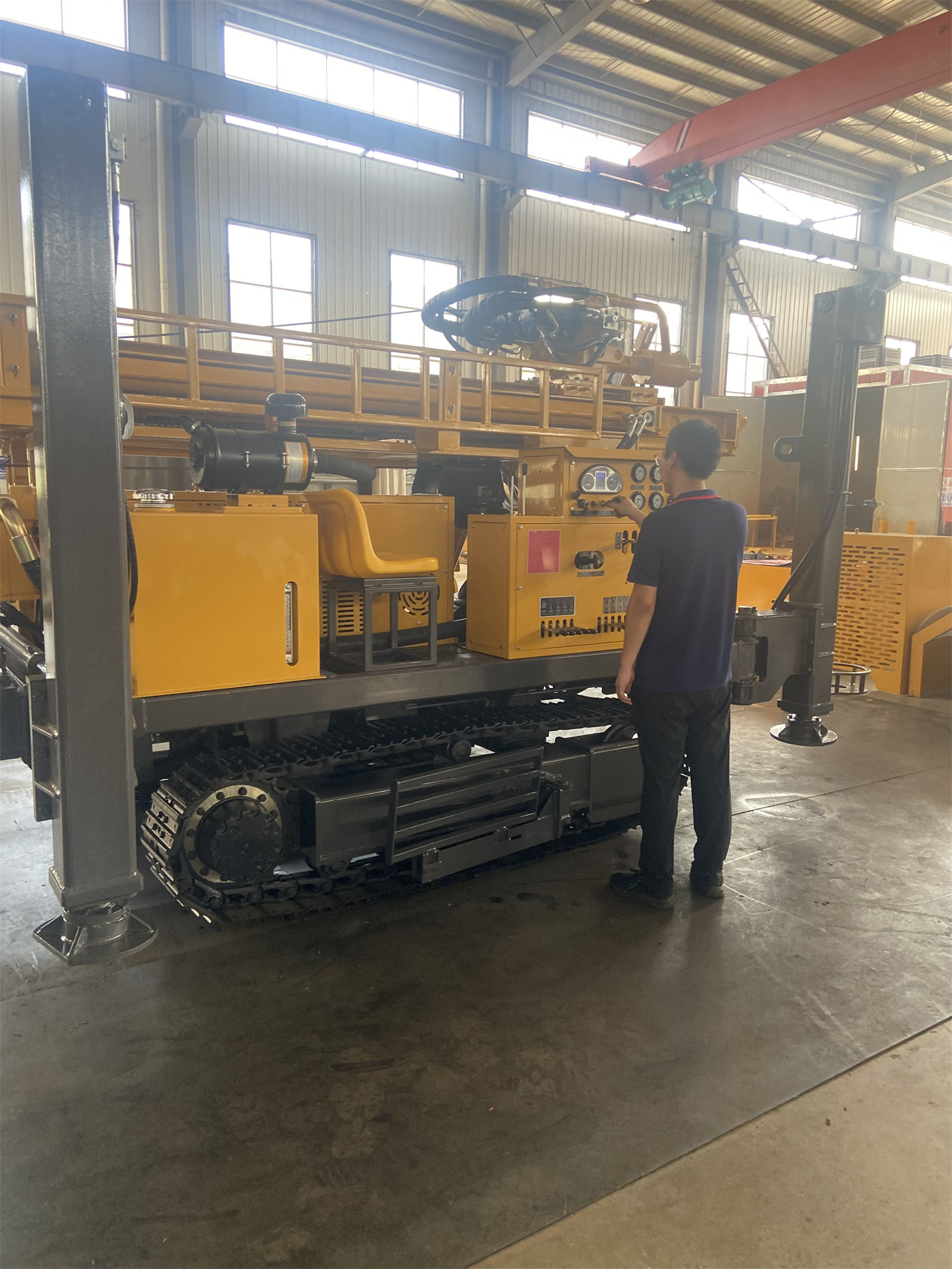
- Whether the project's maximum completed borehole diameter falls within the 105–400 mm range, and the specifications of the drill bit, DTH hammer, or mud rotary drilling tools selected for that diameter.
- A description of the drillability of the main rock formations, such as granite, limestone, sandstone, or weathered rock, soil layers, and gravel overburden.
- The planned drilling technique: DTH down-the-hole drilling, mud rotary drilling, or a combination of upper mud drilling and lower DTH drilling.
The data provided are rotary system capability parameters and do not give efficiency values for different borehole diameter–rock formation combinations. Therefore, 11000 N·m should not be directly understood as covering all depths and all rock formations at a 400 mm borehole diameter. The manufacturer's calculation results for the specific drill string configuration should be taken as the basis.
The 30 T Lifting Capacity Must Be Verified Within the Drill Pipe String and Casing Weight
At 500 m-class well depths, the self-weight of the drill pipes, borehole wall friction, and casing weight increase significantly. The 30 T lifting capacity provides margin for tripping, DTH hammer recovery, and some casing operations. Before purchasing, it is recommended to organize the verification conditions in the following order:
| Verification Item | Information to Confirm with the Project or Manufacturer |
|---|---|
| Drill pipe specifications and length | The WR500S supports 6 m drill pipes. The data list a recommended drill pipe diameter of 89; the complete optional range must be confirmed. Calculate the total weight of the full-hole drill pipe string based on well depth. |
| Borehole friction | Borehole deviation, diameter reduction, rock falls, and mud cake conditions will add extra lifting resistance. The data do not provide a friction coefficient, so this should be judged based on site conditions. |
| Casing operations | The 30 T lifting capacity can be used for some casing operations. The total weight of the casing string, casing running method, and well structure must be calculated separately. |
| Abnormal handling | The data explicitly warn that if tripping resistance is abnormal, the hole should first be cleaned and the borehole wall and drilling tool condition assessed, avoiding direct use of maximum lifting capacity for forced handling. |
Impact of the Telescopic Mast and 6 m Drill Pipes on Procurement Support
The S in WR500S stands for telescopic mast. In transport mode, the equipment's overall dimensions can be shortened, facilitating loading, road passage, and cross-project relocation. After arriving at the site, the mast is extended to support continuous construction with 6 m drill pipes, reducing the number of pipe connections. Before purchasing, the following must also be confirmed:
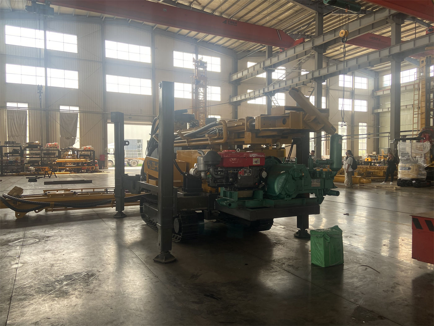
- The overall machine weight is approximately 10.6 T, with dimensions of approximately 6.52 × 1.85 × 2.51 m. Transport vehicle load capacity, road width and height restrictions, and flatbed truck arrangements must be planned in advance.
- After arriving at the site, space for mast extension should be reserved, and the telescopic mast locking, equipment fixing points, and drill pipe bundling status should be checked.
- When using 6 m drill pipes, the mast must be fully extended and reliably secured. High-load drilling should be avoided when the mast is not locked or the site is not leveled.
- During routine maintenance, the telescopic mast guide rails, cylinders, pins, and locking structures are key inspection points.
Associated Requirements for Air Compressors and Mud Systems Based on Rock Formation Techniques
The WR500S supports DTH down-the-hole drilling and mud rotary drilling. For pneumatic DTH drilling, the recommended working pressure is 1.2–3.5 MPa, with air consumption of 16–55 m³/min. When borehole diameter increases, rock becomes harder, well depth increases, or altitude rises, the demand for air compressor displacement becomes higher. Air compressor selection should consider both pressure and flow rate.
- Soil layers, clay, sand layers, and gravel overburden can be stabilized through mud circulation, casing, or other hole stabilization measures before entering rock formations and switching to DTH down-the-hole drilling.
- Fractured zones may experience rock falls, air leakage, sticking, and abnormal cuttings return. Whether to use foam or casing should be judged based on site conditions.
- After entering the main aquifer, the aquifer depth should be recorded promptly, and air supply, hole cleaning, and casing methods should be adjusted according to water inflow.
- The equipment can be optionally equipped with mud pumps, centrifugal pumps, generators, and foam pumps according to project needs. Projects with more loose layers place greater emphasis on the mud system, while hard rock projects rely more on air compressors and DTH hammers.
Operating Conditions and Configuration List to Obtain Before Purchasing
Organizing the following information into an inquiry document is more likely to yield an executable configuration plan than simply requesting a "500-meter water well drilling rig":
- Design well depth, completed well diameter, opening diameter, and final hole diameter, as well as whether casing is required.
- Layered descriptions of the upper overburden and lower rock formations, approximate aquifer locations, and expected water inflow.
- The planned technique combination, and the pressure and displacement of existing or planned air compressors.
- Drill pipe specifications and total length, DTH hammer and drill bit specifications, and the maximum single-piece weight to be lifted.
- Site roads, ground bearing capacity, and relocation methods, used to verify the adaptability of the overall machine's 10.6 T weight, 21° climbing reference, and 1.6 m hydraulic outriggers.
- Requirements for optional items such as mud pumps, centrifugal pumps, generators, and foam pumps.
The data do not provide the WR500S's actual drilling efficiency, torque margin coefficients, or lifting margin coefficients under different borehole diameters and rock formations. These must be calculated by the manufacturer in conjunction with the drill string configuration and on-site hydrogeology. The final well depth should be determined based on local hydrogeology and the location of the water-producing formation. 500 m is the equipment's nominal upper limit and does not mean every well must be drilled to 500 m.