












The WR260 is a 260 m class crawler-mounted fully hydraulic water well drill. To determine whether its 140–305 mm hole diameter and 15 T lifting force match a project, you cannot look only at the maximum drilling depth. You must verify item by item according to hole diameter, expected well depth, aquifer position, and formation type, and then confirm whether the power, air compressor, drilling tools, and hole stabilization process can be matched. The following content is based only on publicly available WR260 product information; where evidence is lacking, it will clearly state that confirmation with the manufacturer is required.
Confirm Three Working Conditions First, Then Discuss Parameter Matching
Before purchasing, three site conditions must be determined first: the designed hole diameter (including the outer diameter of the well casing and screen), the expected completed well depth, and the depth interval of the main aquifer. These three items determine whether the equipment will work normally within its capacity or remain under boundary conditions for a long time. The WR260 public specifications are a maximum drilling depth of 260 m and a drilling diameter of 140–305 mm. Therefore, both well depth and hole diameter should be evaluated with the idea that margin decreases as limits are approached, rather than directly marking the upper limit as feasible.
- The closer the hole diameter is to 305 mm, the higher the required air flow, rotary load, and cuttings removal difficulty usually are, and the air compressor match needs to be more sufficient.
- The closer the well depth is to 260 m, the greater the drill pipe self-weight and hole wall friction, and more attention should be paid to pull-out resistance, hole cleaning effectiveness, and drilling tool wear.
- The aquifer position determines the screen, water stop structure, and well completion process. It cannot be replaced merely by increasing well depth instead of preliminary water exploration judgment.
What Well Completion Needs Do Hole Diameters of 140–305 mm Correspond To?
The WR260's drilling diameter covers 140–305 mm. The information states that this range can correspond to various well casing and submersible pump configurations, but the specific hole diameter to choose should be determined jointly by the well casing outer diameter, filter layer thickness, aquifer type, and water yield requirements.
- If the hole diameter is on the larger side, the amount of rock powder to be discharged per unit time increases, placing higher demands on air compressor displacement, upward return air velocity, and hole cleaning rhythm.
- If the hole diameter is on the smaller side, the space for running the well casing and submersible pump is limited, and post-completion maintenance and well washing are also more likely to be affected.
- The information does not provide a recommended well casing size comparison table for different hole diameters. This part should be based on project hydrogeological data and well completion design.
It should be noted that the parameter table on this site only lists the hole diameter range of 140–305 mm and does not give recommended combinations of each hole diameter with corresponding DTH hammers and drill bits. During purchase, the manufacturer should confirm according to the actual well completion design.
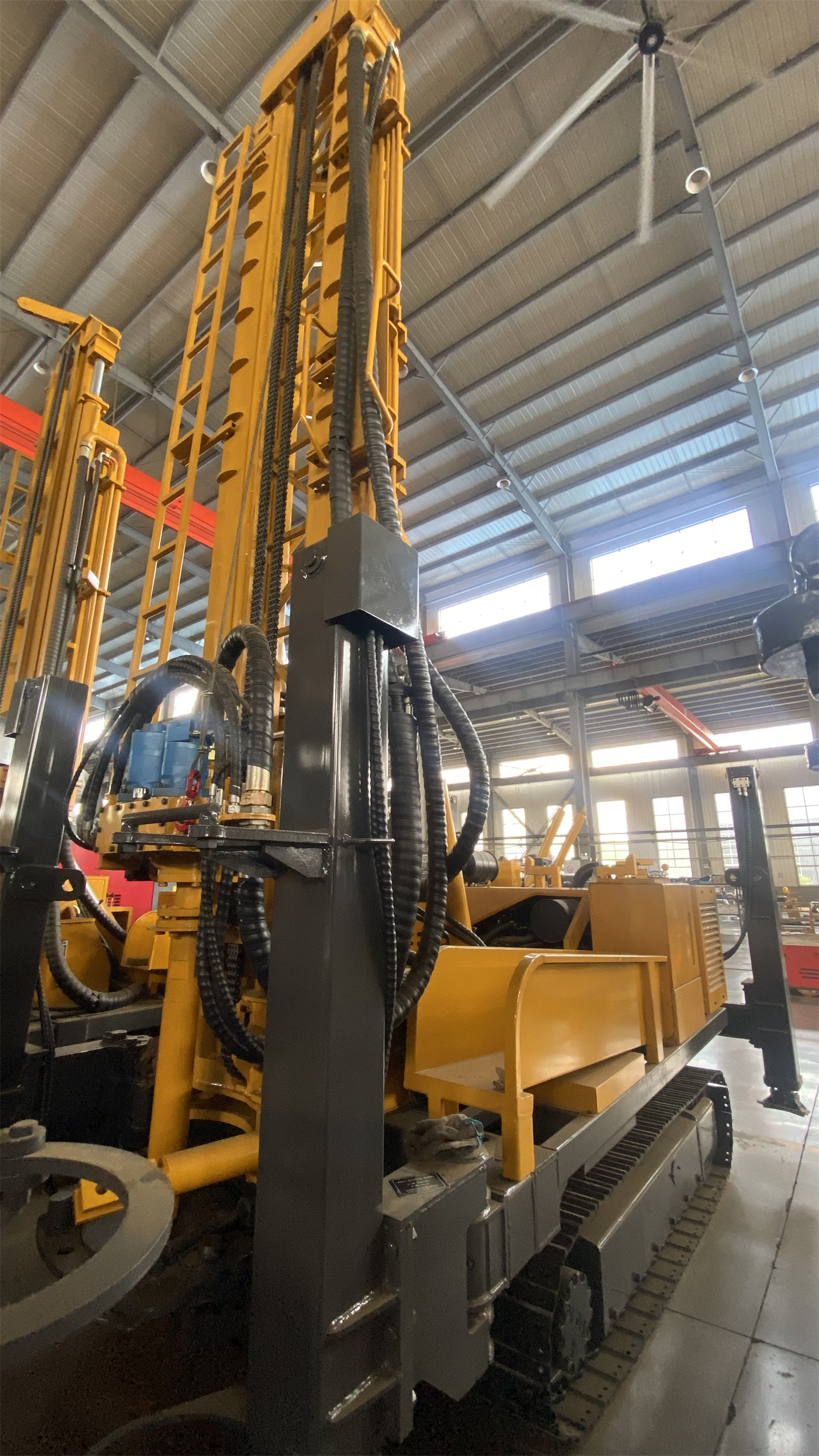
How to Calculate the 260 m Drilling Depth and Well Depth Margin
260 m is the WR260's public maximum drilling depth. In actual projects, "well depth" often includes the overburden section, rock section, aquifer section, and sand settling section. Therefore, the designed water intake depth cannot be directly equated with the drilling depth.
- If the designed well depth is close to 260 m, pull-out resistance, drill pipe thread wear, and cuttings removal status are more likely to become limiting factors.
- The reference drilling efficiency in the information is 10–35 m/h. On-site results will vary significantly with rock formation conditions, and this value cannot be used directly to infer the construction period for a single well.
- If the project requires deeper wells or longer operation in the deep hole section, the equipment class should be re-evaluated rather than relying on a single parameter meeting the standard.
Where Does the 15 T Lifting Force Play a Role?
The WR260's lifting force is 15 T. Public information states that it can be used for normal tripping, drill pipe handling, DTH hammer recovery, and some casing operations. As the borehole deepens, drill pipe self-weight and hole wall friction increase. Whether the lifting force is sufficient depends on the weight of the drilling tool assembly, hole wall stability, and hole cleaning effectiveness.
- When pull-out resistance shows continuous abnormality, the hole should be cleaned first and the hole wall and drilling tools inspected, rather than directly relying on maximum lifting force to force handling. This is an operating principle clearly indicated in the information.
- Whether casing operations are applicable depends on casing specifications, running depth, and hole wall conditions. The information does not give an upper limit for casing specifications that can be run.
- The auxiliary winch lifting force is 1.5 T, used for handling DTH hammers, drill pipes, casing tools, and some on-site auxiliary equipment. It is not the same purpose as the main lifting force.
The Matching Relationship Among Rotary Torque, Single Feed, and Drilling Method
The WR260 uses the DTH hammer drilling method, with rotary torque of 4000–5300 N·m and rotary speed of 45–70 r/min. It can be matched with 76 mm or 89 mm drill pipes and common DTH hammers. The single feed length is 3.3 m, and it can be matched with 1.5 m, 2 m, and 3 m drill pipes. The fast lifting speed of 24 m/min and fast feed speed of 40 m/min in the information are used for drill pipe handling and power head return, and are not equal to the actual penetration rate in the formation.
During DTH drilling, the public reference working air pressure is 1.7–2.5 MPa, and air consumption is 17–31 m³/min. Insufficient air compressor displacement will cause insufficient DTH hammer impact and difficult cuttings removal. When the hole diameter increases, the rock formation hardens, or the altitude rises, a more sufficient air flow is usually required. During purchase, this item needs to be verified together with the air compressor specifications, rather than looking only at the drill rig's own parameters.
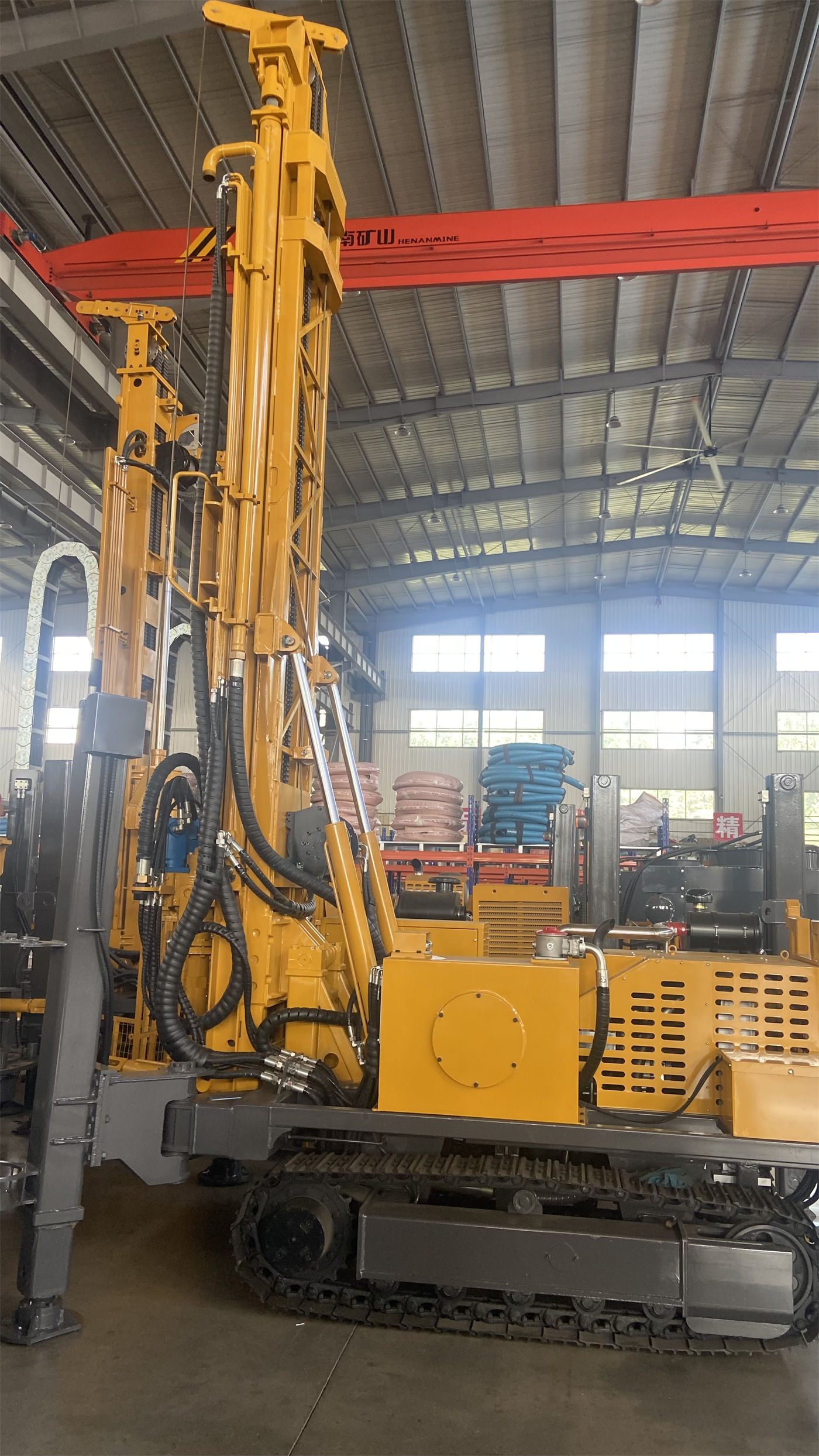
The Impact of Aquifer and Formation Conditions on Matching Judgment
After entering the aquifer, groundwater will change the DTH hammer operation and rock powder discharge status. Air supply and hole cleaning methods should be adjusted according to water inflow, and the main aquifer depth should be recorded. During formal well completion, well casing, screens, and water stop structures must also be configured according to the aquifer position. The following formation conditions directly affect the judgment of whether the hole diameter and lifting force match:
- Soil, clay, sand, and gravel overburden: Direct use of a DTH hammer may cause hole collapse and drilling tool burial. Casing, mud, or other hole stabilization processes should be selected according to the formation, and a stable hole opening and upper hole section should be established first.
- Weathered rock and alternating soft-hard formations: Hole wall falling blocks and diameter reduction are likely. Drilling speed may be fast, but stability is not necessarily ideal. If necessary, casing should be used to protect the upper unstable hole section.
- Fractured zones and fracture-developed formations: Falling blocks, air leakage, and sticking are likely. Excessive feed should be reduced, and continuous cuttings removal and hole cleaning should be maintained.
- Karst caves, fractures, and severely air-leaking formations: Air compressor pressure and flow may be difficult to effectively transmit to the hole bottom. The information suggests that foam, casing, increased air volume, or a change in construction method may be needed.
Under these conditions, the actually usable hole diameter and depth may be lower than the equipment's nominal upper limits. During purchase communication, the formation conditions should be provided to the manufacturer truthfully.
WR260 Main Public Parameter Comparison
| Parameter Item | Public Parameter Value |
|---|---|
| Product Model | WR260 |
| Equipment Type | Compact crawler-mounted fully hydraulic water well drill |
| Maximum Drilling Depth | 260 m |
| Drilling Diameter | 140–305 mm |
| Rotary Torque | 4000–5300 N·m |
| Rotary Speed | 45–70 r/min |
| Lifting Force | 15 T |
| Auxiliary Winch Lifting Force | 1.5 T |
| Single Feed Length | 3.3 m |
| Fast Lifting Speed | 24 m/min |
| Fast Feed Speed | 40 m/min |
| Working Air Pressure (DTH Reference) | 1.7–2.5 MPa |
| Air Consumption (DTH Reference) | 17–31 m³/min |
| Power Configuration | 76 kW diesel engine / optional electric motor power |
| Chassis Type | Steel crawler chassis |
| Travel Speed | Approx. 2.5 km/h |
| Reference Maximum Gradeability | 30° |
| Outrigger Stroke | 1.4 m |
| Overall Weight | 5.7 T |
| Dimensions | Approx. 3900 × 1750 × 2250 mm |
| Width Marked in Information | 2.73 m (original marking is "Width of loading", inconsistent with the overall dimension width of 1750 mm; should be confirmed with formal production technical documentation) |
Items to Verify with the Manufacturer Before Purchase
- For the target hole diameter and expected well depth, provide the drilling tool assembly, DTH hammer specifications, and recommended air compressor displacement for that working condition.
- The power, voltage, and control method of the optional electric motor power. The information does not give specific values, and the formal configuration should prevail.
- The actual meaning of the 2.73 m marking, as well as the dimensions and loading method of the complete machine in transport state.
- The specifications and depth range of casing that can be run under different formation conditions.
- The differences in well completion design for different uses such as agricultural irrigation, rural water supply, and mining area water wells.
- The lithology conditions and testing criteria corresponding to the reference drilling efficiency of 10–35 m/h, to avoid directly applying it to local formations.
Content Already Indicated in the Information Regarding Maintenance and Use
Before daily construction, check the engine, hydraulic system, rotary head, mast, winch, and high-pressure air hose. During operation, observe air pressure, cuttings removal, water return, and equipment temperature. After completion, clean mud and dust, and check drill pipe threads, DTH hammer lubrication, and hydraulic joints. When frequently moving between sites, also check the crawler and loading fixation points. When moving the equipment, retract the mast and assess slope and ground bearing conditions. Before opening the hole, ensure the complete machine is stable; soft ground requires additional pads.
Because actual geological conditions, downhole tools, drilling angle, and operating methods vary, the final drilling efficiency, drilling depth, and well completion effect should be based on on-site working conditions. The above content does not constitute a commitment to the well completion effect of a specific project. Purchase decisions are recommended to be confirmed jointly with local hydrogeological data and the manufacturer's formal technical documentation.