












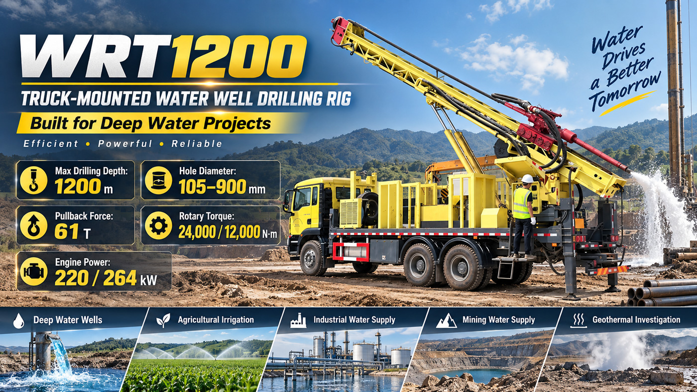
The selection sequence for deep water supply projects usually does not start with how deep a single piece of equipment can drill, but rather works backward from the water use goal. How much stable water output is needed, approximately at what depth the target aquifer lies, and what size well casing and submersible pump must fit into the completed well—these conditions are determined first, and only then does the equipment discussion turn to drilling depth, lifting force, torque, and air compressor. This article uses the published WRT1200 parameters as a sample to explain what each layer constrains in this sequence: maximum drilling depth 1200 m, borehole diameter 105–900 mm, 61 T lifting force, 24000/12000 N·m dual-condition torque, 7/13 m feed stroke, recommended 127 mm drill pipe, overall weight about 32 T. Any parts not covered by the materials on this site are directly marked as to be confirmed.
Layer 1: The water use goal determines whether to enter the 1200 m class
The equipment class is first determined by the project goal, not by the maximum value in the parameter table. The WRT1200 materials list its uses as deep water supply, agricultural irrigation, mining area dewatering, and geothermal investigation. The common feature of these scenarios is that shallow water sources are difficult to meet water volume or stability requirements. If the target aquifer is relatively shallow and water demand is limited, using 1200 m-class equipment does not bring additional benefits, but instead entails greater overall weight and stricter site conditions. Conversely, if hydrological data show that shallow aquifers have insufficient water volume, a mining area needs a more stable water source, or an industrial project needs highly reliable water supply, then the 1200 m-class depth reserve has practical significance.
The conclusion at this layer should come from hydrogeological evaluation, not from equipment samples. The materials clearly indicate that before formal construction, hydrogeological and water quality evaluations should be completed to determine the target aquifer, rather than simply drilling according to the maximum drilling depth.
Layer 2: Hydrology and well completion design determine hole diameter, which in turn changes the load
Borehole diameter is a linking parameter. The WRT1200 covers 105–900 mm, corresponding to conventional deep water wells up to large-diameter groundwater wells. A larger hole diameter facilitates the installation of larger well casing and submersible pumps, but the materials also state that this increases drill string load, casing weight, cuttings removal requirements, and air compressor load. Therefore, hole diameter cannot be understood simply as "the bigger the better," but should be determined in reverse from water output, well casing specifications, and pump type design.
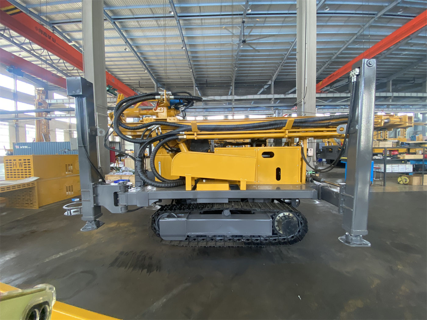
Only after the hole diameter is determined does it come to checking the drill string weight, casing weight, borehole wall friction, and cuttings removal capacity under the combination of that hole diameter and target hole depth. The recommended drill pipe diameter given in the materials is 127 mm, and drill pipe lengths support 3 m or 6 m; 6 m drill pipe can reduce the number of connections, while 3 m drill pipe is more flexible in transportation, manual coordination, and confined sites. This set of choices belongs to the interface between borehole design and on-site organization, not purely equipment parameters.
Layer 3: Lifting force, torque, and feed stroke each govern a stage of the process
At this layer, the parameters truly begin to participate in trade-offs. The WRT1200's 61 T lifting force, 13 T axial pressure, 24000/12000 N·m dual-condition torque (corresponding to 75/150 r/min dual speed), and 7/13 m propulsion/feed stroke respectively correspond to different processes and should not be compared together.
| Parameter | Value | Main constraint |
|---|---|---|
| Maximum drilling depth | 1200 m | Target aquifer depth reserve |
| Borehole diameter | 105–900 mm | Well casing and submersible pump configuration |
| Lifting force | 61 T | Deep hole drill string and partial casing operations |
| Dual-condition torque | 24000/12000 N·m | Switching between large-diameter hard rock and stable formations |
| Feed stroke | 7/13 m | Connection frequency and continuous drilling efficiency |
| Overall weight/dimensions | About 32 T / 11.5×2.25×3.2 m | Road and drilling site access conditions |
The significance of lifting force increases with hole depth: drill pipe self-weight, casing weight, and borehole wall friction all rise, and higher lifting capacity facilitates deep hole tripping, DTH hammer recovery, and partial casing operations. There is an important boundary in the materials—if tripping resistance is abnormal, the hole should be cleaned first and the condition of the borehole wall, drill string, and sediment assessed, rather than simply relying on maximum lifting force to pull hard. This statement shows that lifting force is an operational capability, not a method for handling downhole accidents.
The use of dual-condition torque is segmented matching: low-speed high torque is more suitable for large-diameter, hard rock, and high-friction hole sections, while the high-speed gear is suitable for stable formations with less resistance. During construction, switching should be done promptly according to drill string load, cuttings return, and torque changes. Understanding the two torque figures as two speed gears is not accurate.
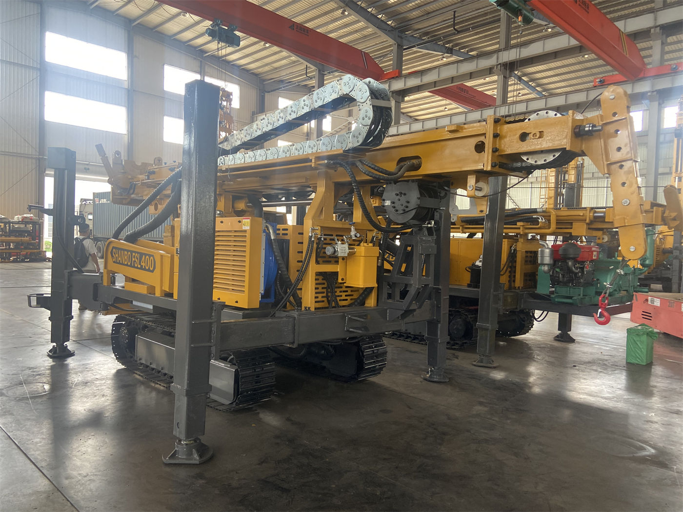
The 7/13 m feed stroke is a final configuration option. A longer stroke can reduce power head return and drill pipe operation frequency, making it more suitable for deep hole projects pursuing continuous drilling efficiency; the 7 m configuration more easily balances overall structure and site adaptability. The materials also note that the final configuration should be based on supplier technical confirmation documents.
Layer 4: The process route determines the air compressor and supporting equipment, not just the main machine
Deep water supply projects commonly have multiple process routes, and the WRT1200 materials cover some of these conditions. When using DTH hammer drilling, the recommended working air pressure is 1.65–8 MPa, and air consumption is 16–120 m³/min; after entering relatively intact hard rock such as limestone, sandstone, and granite, medium and high-pressure DTH hammers can be configured. There is a clear matching logic in the materials: if only pressure is met but displacement is insufficient, it may still lead to insufficient impact, difficult cuttings removal, and bottom-hole cuttings accumulation. That is, the air compressor's pressure and displacement must be checked together, not just one of them.
The upper loose layer is another constraint. Soil, clay, sand, and gravel layers can use mud rotary, casing, or other hole stabilization methods; for 1200 m ultra-deep wells, the stability of the upper hole section is especially important, because early collapse, diameter reduction, or casing problems will significantly increase subsequent deep construction risks. Weathered rock and fault fracture zones are prone to block falling, diameter reduction, air leakage, and sticking. When entering these hole sections, excessive rapid advancement should be reduced, hole cleaning should be strengthened, and casing or foam assistance should be used promptly according to borehole wall conditions. After entering the main aquifer, groundwater will change DTH cuttings removal and downhole pressure conditions. The depth of the main water-producing layers should be recorded, and the air supply, hole cleaning, and casing plans should be adjusted. At the well completion stage, the filter pipe, sealing section, and final pump type should be designed in combination with aquifer distribution.
Layer 5: Relocation conditions and site conditions should be checked separately
The value of a truck-mounted platform is reflected in multi-hole and cross-regional projects. The WRT1200 integrates the main drilling system on a truck-mounted chassis. Compared with solutions that rely on flatbed trucks for frequent loading and unloading, it is more suitable for road relocation between mining areas, industrial parks, farms, and different cities, and can also reduce repeated loading, unloading, and lifting organization costs. However, the materials also point out that using a direct mast structure rather than a telescopic mast has the cost of a more fixed transport profile. Before construction, road height limits, entry space, and site clearance should be confirmed.
The overall weight is about 32 T, and transport dimensions are about 11.5×2.25×3.2 m. Therefore, before project entry, road width, bridge load capacity, turning radius, site bearing capacity, and overhead obstacles need to be verified. Road conditions in mining areas may be complex, and slope, turning, and drilling site bearing conditions should all be included in the confirmation scope. These are site conditions and are not automatically solved by truck mounting.
Matters to confirm with the supplier
This article is based only on the published WRT1200 parameters. The following content does not provide specific values or conclusions in the materials on this site and should be verified before formal projects: the well completion plan corresponding to the target aquifer depth and water output; the air compressor pressure and displacement combination corresponding to specific hole diameters; formation temperature, casing grade, and cementing requirements (for geothermal projects); and the final configuration of 7 m or 13 m feed stroke and 220 kW or 264 kW diesel power. The recommended drill pipe diameter and air pressure range given in the materials are suggested values, and the actual configuration should be based on supplier technical confirmation documents and project hydrological design.