












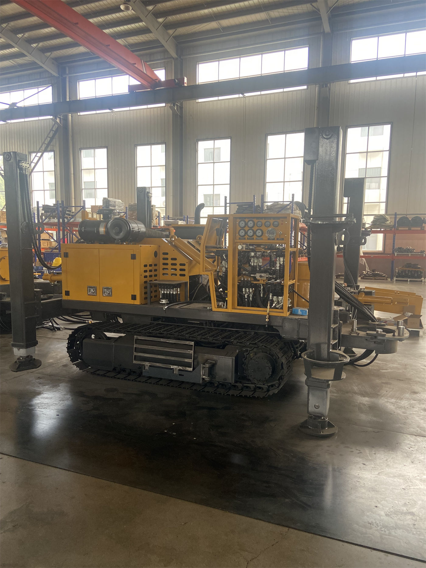
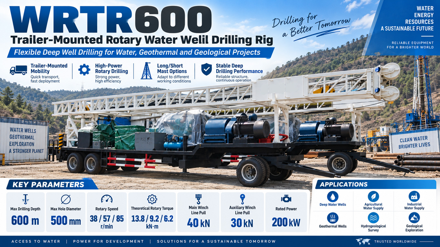
In the WRTR600 parameter table, the rotary table section lists 38 / 57 / 85 r/min, followed by theoretical torques of 13.8 / 9.2 / 6.2 kN·m. These six numbers are arranged in three groups, and the structure itself conveys information: as speed increases, torque decreases. Understanding these three ranges as "three speed options" is not incorrect, but it misses what they truly constrain—how heavy a drilling tool string and how large a hole diameter the same rig can drive at different ranges.
The following discussion focuses only on this set of parameters published on this site, without speculating on formation efficiency or penetration rates not provided in the materials.
Why Speed and Torque Are Inversely Related
Rotary table speed and theoretical torque come from the same power and transmission chain. Given a fixed input power, the higher the speed, the lower the torque available for rotation. 38 r/min corresponds to approximately 13.8 kN·m, while 85 r/min corresponds to approximately 6.2 kN·m—the torque difference between the two ends exceeds a factor of two.
This also illustrates the difference between "three ranges" and "stepless speed regulation" in terms of description: three ranges provide three definite speed-torque combinations, each corresponding to a category of working conditions, rather than a continuously adjustable curve. The materials provide theoretical torque; actual available torque is also affected by transmission efficiency, downhole friction, and operating methods.
Which Hole Section Each Range Corresponds To
The materials' interpretation of this set of parameters is clear in direction: the low-speed range has higher torque, suitable for larger hole diameters, heavy drilling tools, and formations with greater resistance; higher speeds are suitable for drilling stages with less resistance.
| Range | Speed | Theoretical Torque | Application Direction per Materials |
|---|---|---|---|
| Low-speed range | 38 r/min | Approx. 13.8 kN·m | Larger hole diameters, heavy drilling tools, formations with greater resistance |
| Medium-speed range | 57 r/min | Approx. 9.2 kN·m | Drilling stages between the two extremes |
| High-speed range | 85 r/min | Approx. 6.2 kN·m | Drilling stages with less resistance |
It should be noted that these three directions are qualitative descriptions from the materials, without a conversion table indicating which formation type corresponds to which range. The actual timing for shifting ranges still depends on returns in the hole, drilling tool rotation resistance, and changes in penetration rate.
Speed Ranges Cannot Be Considered in Isolation
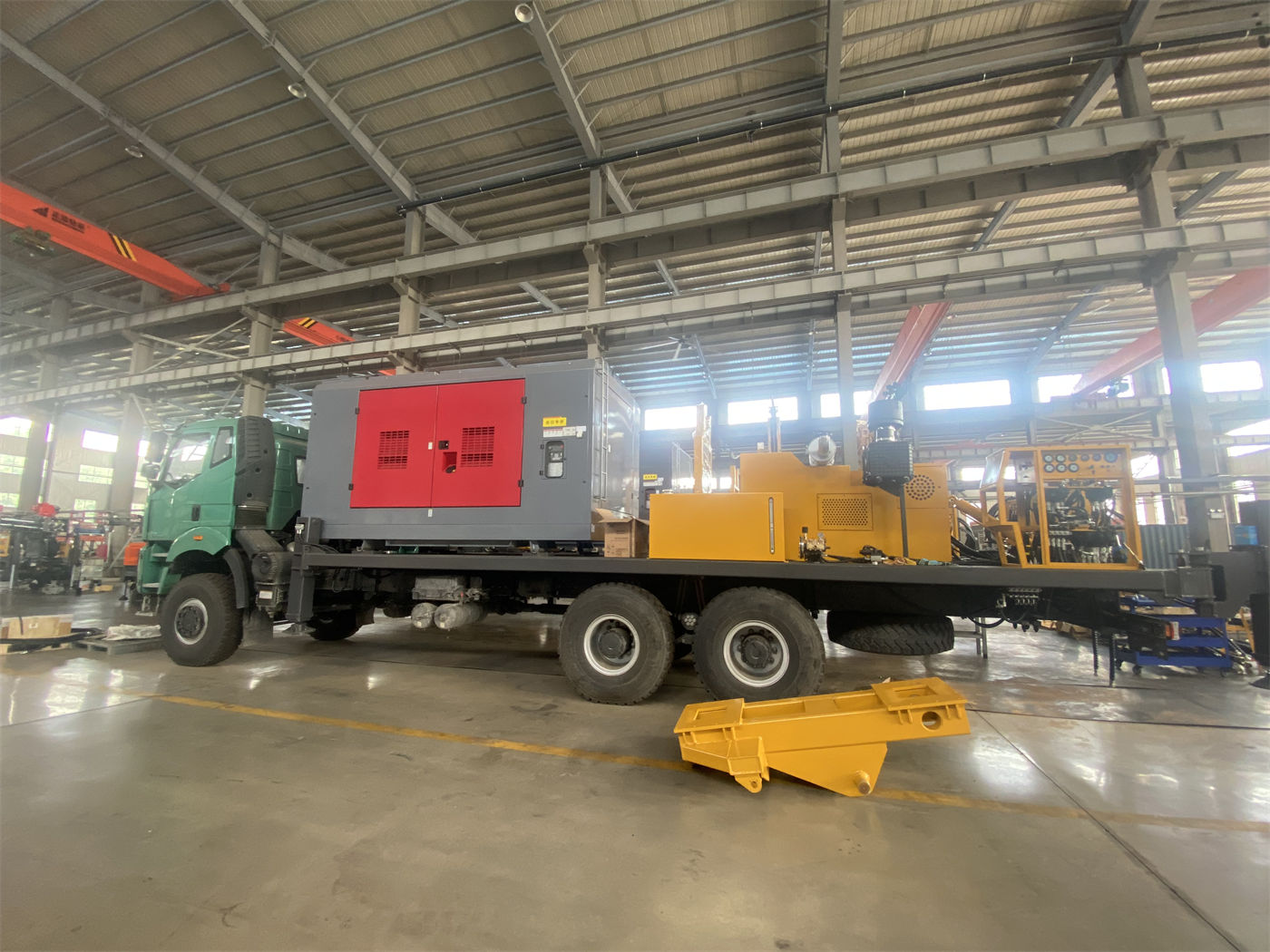
Treating speed as an independent operating parameter easily overlooks several other constraints on the same equipment. The WRTR600 has a maximum drilling diameter of 500 mm and a rotary table through-hole diameter of 500 mm; the swivel has a maximum load of 30 T and an inner diameter of 63.5 mm; the mud pump is a 3NB-130 with a specified displacement of 8.4–16.6 L/s, a rated working pressure of 5–10 MPa, driven by a 90 kW motor.
The rotary table being able to turn does not mean the hole is being cleaned properly. As hole diameter increases and depth increases, both the volume of cuttings and the return distance increase, and the mud pump displacement and mud properties must keep up with the penetration created by rotation. Low-speed, high-torque ranges address "whether it can turn"; displacement and wall protection address "whether cuttings can be carried out and whether the hole wall can be maintained." If either is lacking, range selection cannot be implemented.
Coordination with the Winch and Swivel
The choice of speed range also affects drill string management. The main winch has a single-line pull of 40 kN, and the auxiliary winch has a single-line pull of 30 kN; the swivel has a maximum load of 30 T. As hole depth increases, the drill string's own weight and wall friction gradually rise. If the high-speed range is used for extended periods during deep-hole stages, changes in rotation resistance, drilling tool wear, and downhole loads need to be considered together with the matching of the winch, kelly, and drill pipes—not just the rotary table.
In the materials, the short mast version is equipped with a 7.5 m kelly and 5.5 m drill pipes, while the long mast version is equipped with a 10.5 m kelly and 9 m drill pipes. Different kelly and drill pipe lengths mean different numbers of connections and different single-run lengths, which affect the duration of continuous drilling in a given range and, consequently, the frequency of range changes.
No Quantitative Conclusions on Range Shifting Itself
The materials on this site do not provide penetration rates, formation codes, or shifting thresholds for each range, nor is there a fixed rule that a certain formation must use a certain range. Only three points can be confirmed: the speed and theoretical torque values of the three ranges; the torque relationship where low speed exceeds high speed; and the fact that different ranges are directed by the materials toward different resistance conditions.
Formation, drilling tools, mud circulation, and downhole resistance jointly determine the actual load, and the final drilling parameters should still be based on on-site conditions. To further determine at what depth a particular well should shift to which range, what is needed is the project's hole diameter design, drilling tool assembly, and formation profile—none of which are covered by the existing parameter table.
Questions to Ask First When Reading the Speed Table
- Can the theoretical torque of this range drive the current drilling tool assembly?
- At the current hole diameter and depth, is the 3NB-130's displacement sufficient?
- Is there still margin between the swivel's 30 T load and the drill string's own weight?
- How will the drill pipe length corresponding to the selected mast type change the rhythm of connections and range shifts?
The three speed ranges are not three parallel speed buttons, but three ways the same rig allocates power. Once this relationship is clear, and then hole diameter, pump displacement, and lifting force are considered, the parameters connect with one another.