












In the WR500RCE product materials, there is a fairly straightforward statement: it differs from the RC model intended for mineral sampling, and the product focus is on deep-hole cuttings removal, hard rock water wells, mining area water supply, and hole completion in complex formations. This statement is not embellishment but a precondition for reading the material. For the same crawler-mounted reverse circulation drilling rig, if the project objective is well completion, the parameters should be read according to the well completion process; if the project objective is continuous cuttings sampling, the same-named parameters will fall into a different set of judgments. This article focuses only on this distinction, explaining which fields in the WR500RCE materials belong to water well use, which fields are explicitly assigned in the materials to the sampling model side, and which items can be separated first when reading the materials.
The use column is the first dividing line in this material
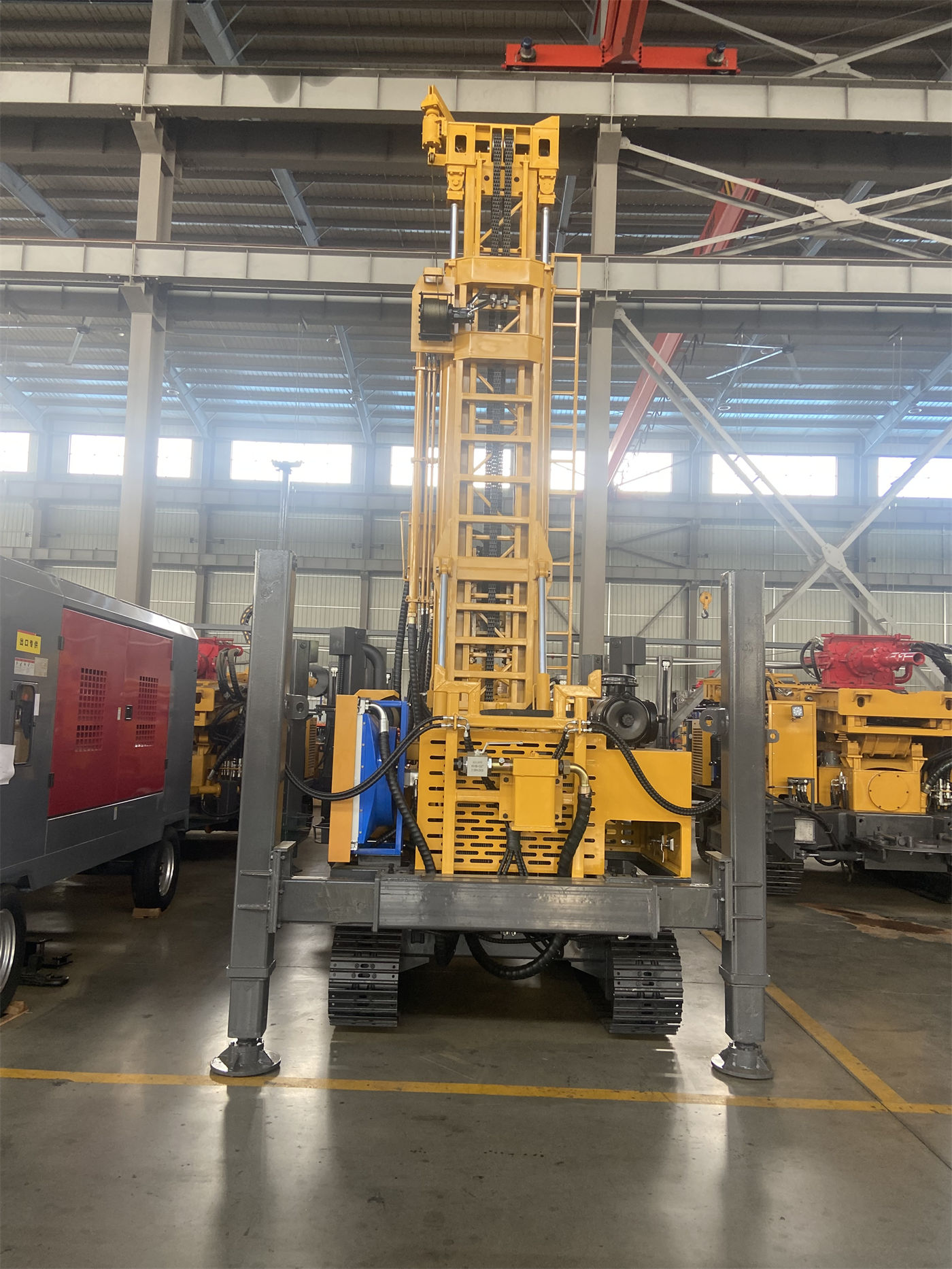
The applicable working conditions given in the WR500RCE materials are a set of well completion directions: deep water wells, agricultural irrigation, mining area water supply, and dewatering drilling. The corresponding parameters are maximum drilling depth 500 m, drilling diameter 140–400 mm, 132 kW diesel power, 300 kN lifting force, 150 kN feed force, rotary torque 8000–12000 N·m, and rotary speed 40–160 r/min.
The same passage also states that this model's process method is air-lift reverse circulation, which uses compressed air to establish return flow in the inner pipe and carries cuttings and drill spoil from the hole bottom back to the surface through the inside of the drill pipe. Here, although both "spoil return" and "sample return" pass through the inner pipe, their purposes differ: water well use focuses on hole bottom cleanliness, reducing regrinding and settled cuttings, while sampling use focuses on whether cuttings can form representative samples by depth. The materials do not merge these two matters, and they should not be merged when reading.
In the well completion process, which parameters are read together
If the material is read from the water well direction, at least three groups of relationships among the parameters need to be viewed together rather than looking at a single extreme value.
| Process focus | Corresponding values in the materials | Associated fields |
|---|---|---|
| Deep-hole drill string handling | 300 kN lifting force, 150 kN feed force | Drill pipe specifications 1.5/2/3/6 m, feed stroke 3.3 m or 6.6 m |
| Hole diameter and rock formation load | Drilling diameter 140–400 mm, torque 8000–12000 N·m | Rotary speed 40–160 r/min |
| Cuttings removal and hole bottom cleanliness | Working air pressure 1.7–3.5 MPa, air consumption 17–42 m³/min | Air compressor displacement, hole diameter, hole depth, altitude |
The relationships among these three groups are written separately in the materials. Lifting force corresponds to the increase in drill pipe self-weight, hole wall friction, and casing weight in 500-meter-class drilling; torque corresponds to large-diameter, hard rock, and high-friction working conditions; air pressure and air consumption correspond to the air-lift reverse circulation system, and the materials clearly state that when hole depth increases, hole diameter becomes larger, rock formations become harder, or construction altitude rises, the required displacement will increase. Any one item alone is not enough to indicate whether this equipment can complete a given well.
Where sampling use is placed in the materials
The main text of WR500RCE includes "differs from the RC model intended for mineral sampling" in the product description, but the given parameter list does not include fields such as sample splitting accuracy, sample numbering management, or continuous sample return capability. Other materials on this site involving sampling use have their own parameter systems for their models; for example, the verification items corresponding to WR500RC-CS3 are sample depth marking and data traceability, and the verification items corresponding to WR600RC-CS3 are splitting accuracy and contamination prevention management. These contents are not part of the published information for WR500RCE and cannot be directly applied to this model.
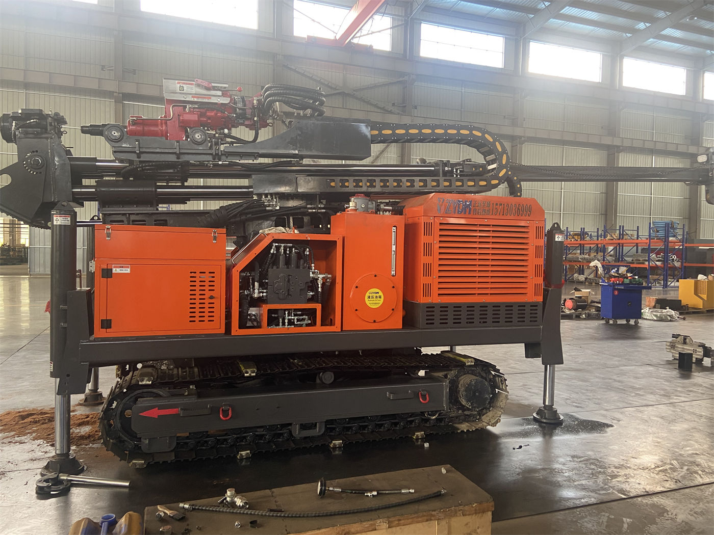
Therefore, when the project objective is mineral sampling, the portion that the WR500RCE materials can answer is limited: they can explain the deep-hole cuttings removal path and hard rock drilling capability, but they cannot answer for the project whether sample representativeness and numbering management meet the requirements. Such questions require separately verifying the configuration of the sampling system, and the materials on this site do not provide corresponding fields for this model.
Several places where the two uses are easily confused
The wording in the materials has already drawn the boundary in the text, but it is still easy to slip past when reading, mainly in these places.
- Treating "reverse circulation" as a unified label. In the materials, the reverse circulation description of WR500RCE immediately follows deep-hole cuttings removal and hole bottom cleanliness; the process objective is hole completion, not sampling.
- Treating the 500 m drilling depth as the sampling hole depth. 500 m is the maximum drilling depth, and the materials clearly state that the final well depth should still be determined by hydrogeological data and the actual water-producing layer.
- Treating the 140–400 mm hole diameter as the sampling hole diameter range. In the materials, this range corresponds to the design space for well casing size, submersible pump, and expected water yield.
- Treating the 8000–12000 N·m torque as a pass for all formations. The materials explain this range under large-diameter, hard rock, and high-friction working conditions, and also state that higher rotary speed is selected only in stable hole sections with lower resistance.
Several items that can be confirmed first when reading this material
Reading in the order of the materials, the items that can be confirmed first include: whether the project objective is well completion or sampling; if it is well completion, whether the target well depth, well diameter, aquifer depth, and well casing plan have been determined; if it is sampling, which system should handle sample splitting, numbering, and contamination prevention requirements. The published parameters of WR500RCE can only cover the equipment capability portion of the former type of question.

The materials also list a series of on-site inspection items: high-pressure air hose, joints, safety rope, rotary head, tracks, mast, and hydraulic system; during drilling, observe changes in air pressure, cuttings return, water return, and torque; after completion, clean the drilling tools and reverse circulation channel. These contents fall within the scope of routine inspection. Actual geological conditions, downhole tools, drilling angle, and operating methods vary, and the final drilling effect cannot be judged solely from the parameter table.
Parts that need to be verified with the supplier
The following items are not fully covered in the WR500RCE materials verified on this site and need to be verified separately during the inquiry or technical confirmation stage: the air compressor displacement configuration required under different hole diameters and hole depths; the combined selection of foam, casing, and drilling methods in fractured zones and air-leakage formations; whether a separate sampling system is required for sampling use, and the corresponding sample management process. The configurable items mentioned in the materials include reverse circulation DTH hammer, drill bit, drill pipes of different specifications, casing tools, air compressor, high-pressure air hose, oil mist lubricator, foam pump, and generator, etc. The materials do not provide a unified answer as to whether all of them need to be configured for a specific project.