












The WR260 documentation describes the site in only two sentences: the crawler chassis facilitates relocation within village roads, field roads, and gravel sites; the equipment dimensions are approximately 3900 × 1750 × 2250 mm, making it easier to enter factory areas and space-constrained construction areas compared with large deep water well drilling rigs. These two sentences are the starting point of this article. Village roads and field ridges are not roads built for drilling rigs to travel on; their width, turning patterns, and ground bearing capacity are not designed according to equipment dimensions. Therefore, what truly determines whether the WR260 can be driven in as planned are several on-site conditions unrelated to the parameter table.
First, dimensions: what 3900 × 1750 × 2250 mm means on a village road
The overall dimensions given in the documentation are approximately 3900 mm long, 1750 mm wide, and 2250 mm high. The width of 1750 mm determines whether it can pass through continuous narrow sections, the length of 3900 mm determines how much turning and reversing clearance is needed, and the height of 2250 mm relates to whether there are low branches, door frames, overhead lines, or temporary sheds along the route.
These three items are the overall outline of the complete machine, not a detachable section. The documentation also lists a 2.73 m parameter labeled "Width of loading," whose name is inconsistent with the 1750 mm overall width. This article retains it only as labeled in the documentation and does not interpret it as the actual transport width; the final definition should be confirmed with formal production technical documentation. Transport-related issues also need to be checked separately.
Steel tracks and relocation distances corresponding to a 2.5 km/h travel speed
The WR260 uses a steel track chassis, with a travel speed of about 2.5 km/h and a reference maximum gradeability of 30°. Steel tracks provide good traction and stability on gravel ground, rural roads, and mining sites, but the speed itself determines that it is more suitable for short-distance self-relocation rather than replacing transport vehicles for long-distance movement.
At an estimated 2.5 km/h, a two- to three-kilometer village road would take hours of pure travel time; if repeated reversing, yielding, or obstacle avoidance is required along the way, the actual time consumed will continue to increase. The documentation recommends that the mast should be retracted during equipment relocation and that slope and ground bearing conditions should be assessed—these two items are not formal steps on rural roads; soft soil subgrades, temporary water crossings, and field ridges loosened after rain are all situations that need to be clearly assessed before deciding.
The 1.4 m leg stroke solves leveling, not the site itself
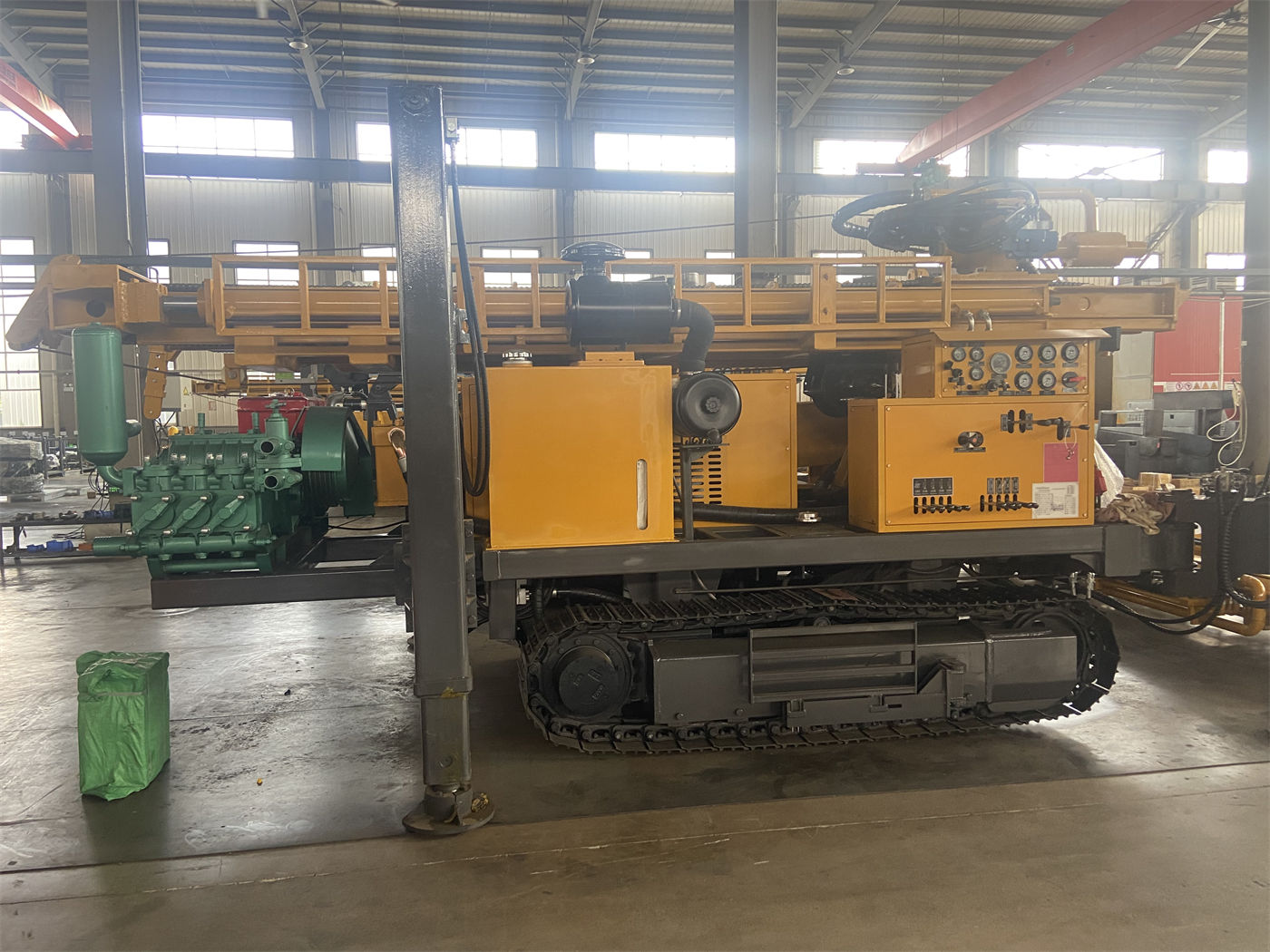
The WR260 has a high leg stroke of 1.4 m, which can support and level the equipment on mildly uneven ground. The documentation also states: soft ground requires additional pads to prevent leg settlement from causing mast tilt and hole position deviation. In other words, the object of leg adjustment is posture, not foundation bearing capacity.
The working surfaces of farmland and orchards are often cultivated layers with insufficient compaction; temporary parking spots on both sides of village roads may be backfilled soil or slope-adjacent positions. Such sites may continue to settle after the legs are extended. Ensuring the stability of the complete machine before drilling usually also requires placing pads under the legs and, based on on-site judgment, determining whether additional ground treatment is needed.
Different sites mean different concerns for the same equipment
The documentation lists the applicable scenarios of the WR260 as rural water supply, agricultural irrigation, farms, factories, construction sites, and small mining area water supply. The equipment conditions for these scenarios are common, but the site concerns are not the same.
- Village roads and communities: Concerns include passage width, low obstacles along the route, temporary parking spots, and scheduling of working hours around residential areas.
- Farmland and orchards: Concerns include field ridge bearing capacity, avoidance of crops and irrigation/drainage facilities, and travel routes for moving between hole positions for multiple wells.
- Farms and pastures: Concerns include continuous passage conditions on hardened or semi-hardened internal roads and the positional relationship with existing water and power supply facilities.
- Small mining areas and survey camps: The documentation mentions that the crawler chassis facilitates movement on gravel roads and generally uneven ground in mining areas, while also noting that when the proportion of hard rock is high, matching the DTH hammer and air compressor should be emphasized.
- Factories and construction sites: Concerns include door opening height, turning radius of factory passages, and parking methods in space-constrained areas.
These are differences in site conditions, not differences in equipment capability. When the same WR260 enters different sites, the matters to be addressed first are different.
Repeated procedures when relocating between multiple wells
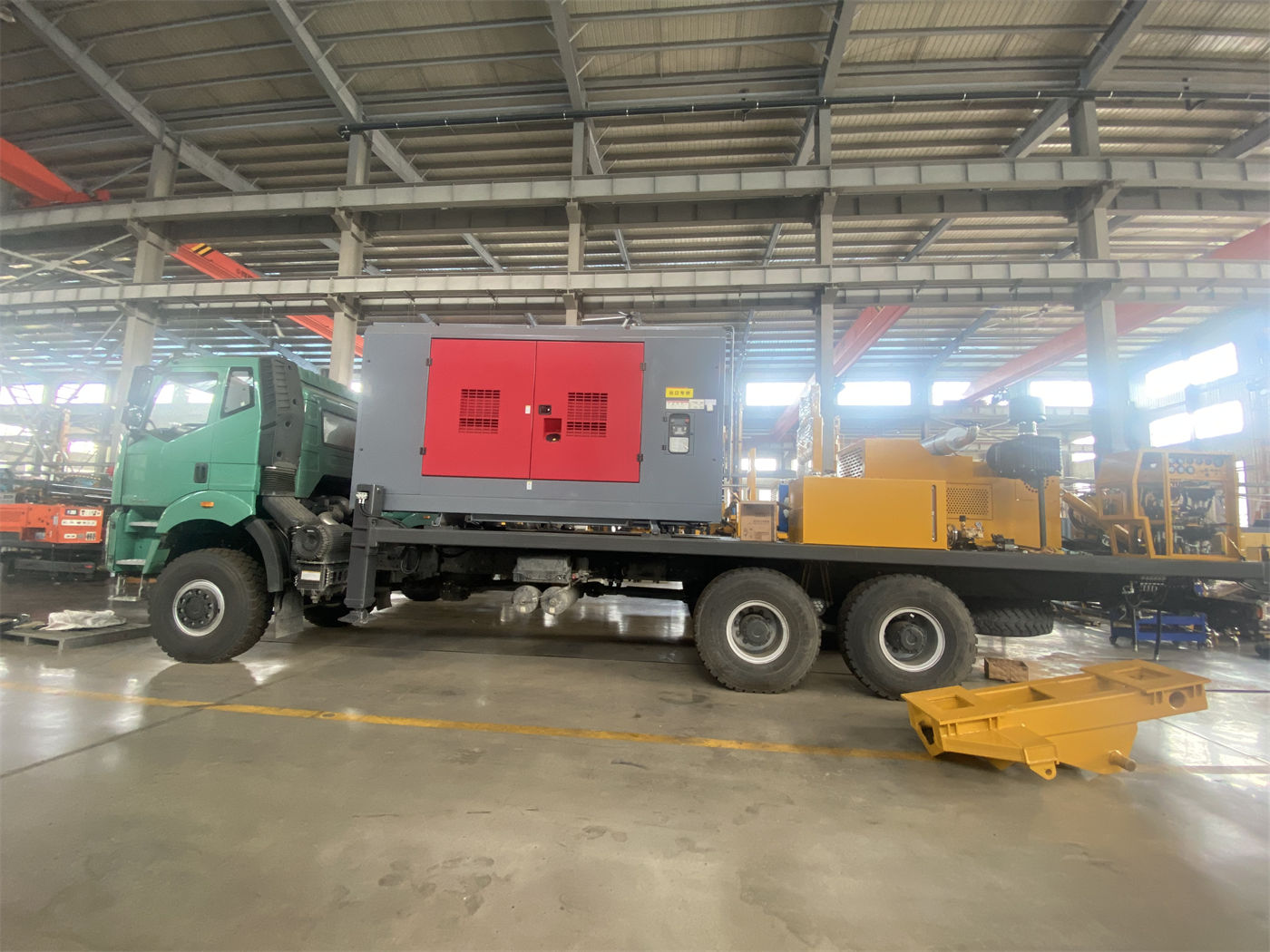
Construction teams that need multiple irrigation wells will repeat the relocation action many times. The documentation mentions that the compact body and strong maneuverability help reduce hole position transfer time. Which links this "reduction" comes from can be inferred from the overall machine conditions: the equipment dimensions are relatively compact, and a single advance length of 3.3 m can match 1.5 m, 2 m, and 3 m drill rods, reducing auxiliary time for power head return and rod connection.
However, relocation time also includes mast retraction, leg raising and lowering, crawler travel route selection, hole position realignment, and leveling. The documentation does not provide time figures for these procedures, and this article does not substitute them as a basis; actual conditions and operating methods should prevail.
Parts of the working scenario related to formation conditions
The site determines whether the equipment can be positioned; the formation determines how to drill after positioning. The WR260 documentation provides several boundaries according to formation, directly related to scenario judgment:
- For relatively intact rock formations such as limestone, sandstone, and granite, drilling is possible after matching appropriate DTH hammers, drill bits, and air compressors; in hard rock, attention should be paid to drill bit wear, DTH hammer lubrication, and cuttings discharge status.
- Weathered rock and alternating soft-hard formations are prone to block falling and hole shrinkage; advancement and rotation should be adjusted in a timely manner according to drilling resistance, and casing should be used when necessary to protect unstable upper hole sections.
- Directly using a DTH hammer in soil layers, clay, sand layers, and gravel overburden may cause hole collapse and drill burial; casing, mud, or other hole stabilization processes should be selected.
- In fractured zones and formations with developed fissures, excessively fast advancement should be reduced, continuous cuttings discharge and hole cleaning should be maintained, and casing or foam assistance may be considered for thicker fractured zones.
- For aquifers and strong water inflow conditions, the air supply and hole cleaning method should be adjusted according to water inflow, and the depth of the main aquifer should be recorded.
- In karst caves, open fissures, and formations with severe air leakage, pressure and flow may be difficult to effectively transmit to the hole bottom; the process should be adjusted according to the degree of air leakage or the air volume should be increased.
The documentation also states that increasing well depth alone cannot replace preliminary water-finding judgment. Well depth, well diameter, filter pipes, and sealing intervals should be determined in combination with aquifer position, expected water yield, and local water quality requirements.
These items are often not determined by the drilling rig on site
Looking at the above groups of conditions together, some are directly related to the WR260, while others are outside the scope of the drilling rig.
| Condition | Degree of relevance to WR260 | Who needs to address it before entering the site |
|---|---|---|
| Passage width and height | Constrained by overall machine width of about 1750 mm and height of 2250 mm | Construction party on-site survey |
| Road surface and parking spot bearing capacity | Leg stroke of 1.4 m can adjust posture; pads are additional measures | Construction party judges according to ground conditions |
| Relocation distance | Travel speed about 2.5 km/h, maximum gradeability reference 30° | Construction party arranges transport or self-travel |
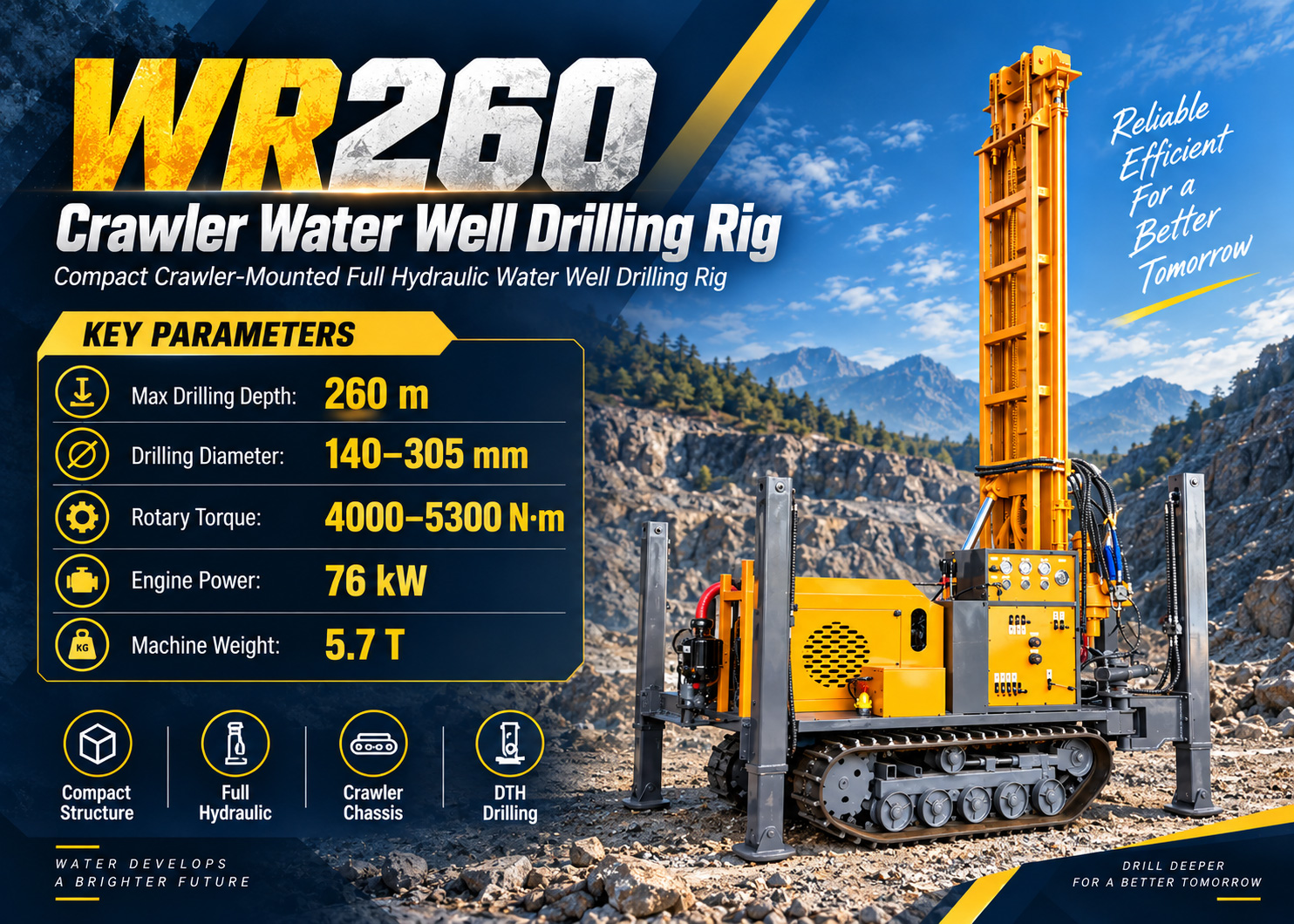
| Well location and well depth | Maximum drilling depth 260 m, hole diameter 140–305 mm | Determined in combination with hydrogeological data |
| Formation and process | Select DTH hammer, casing, or mud processes according to rock formation | In combination with survey and on-site feedback |
The division of labor in the table is only a general summary. Parts not covered by the documentation, such as the actual passability of a specific village road, cannot be inferred from the parameter table and must be confirmed on site.
Matters not answered by the documentation that need to be confirmed with the manufacturer or on site
- The parameter labeled 2.73 m as "Width of loading" is inconsistent with the actual overall width of 1750 mm; its definition should be confirmed with formal production technical documentation.
- The final motor power, voltage, and control method of the optional electric motor power scheme are not given as specific values in the documentation.
- Actual drilling efficiency, drilling depth, and well completion results under different formation combinations are explicitly stated in the documentation to be subject to on-site working conditions; the reference drilling efficiency is 10–35 m/h, a wide range that cannot be used as a single-point commitment.
- The reference working air pressure for DTH drilling is 1.7–2.5 MPa and the air consumption is 17–31 m³/min, which need to be matched with the air compressor according to hole diameter, rock hardness, and altitude; insufficient air compressor displacement will cause insufficient impact and difficult cuttings discharge.
- Specific plans involving transport, lifting, and loading fixation need to be determined separately in combination with local road conditions and the actual state of the equipment.
Before daily construction, check the engine, hydraulic system, rotary head, mast, winch, and high-pressure air hose; during operation, continuously observe air pressure, cuttings discharge, water return, and equipment temperature; after completion, clean mud and dust, and check drill rod threads, DTH hammer lubrication, and hydraulic connectors; during frequent relocation, also check the tracks and loading fixation points. The above content is the inspection items listed in the documentation and does not constitute any operating step recommendations.