












If you only look at the maximum drilling depth column, the distance between a 750 m class and a 600 m class water well drilling rig is just one line of numbers: 750 m versus 600 m. But after comparing the WR750S specification table item by item, you will find that this 150 m does not appear separately in any single field; instead, it is distributed across lifting force, drill pipe specifications, mast structure, rotary torque, and overall weight. When selecting a rig, focusing only on drilling depth can easily cause you to overlook the several conditions that truly determine whether a well can be completed.
Start with the most direct layer: drill string weight and friction are handled by lifting force
The WR750S data specifies a lifting force of 40 T and an axial pressure of 6 T. The typical magnitude for 600 m class equipment in this field is usually below 40 T. The difference corresponds exactly to the increment in the self-weight of the entire drill string, borehole wall friction, and tripping resistance in deep holes.
For every additional section of hole depth, the self-weight of the drill string increases linearly, while friction is related to borehole wall conditions, borehole curvature, and hole cleaning quality, and does not necessarily change steadily with depth. This means that part of the margin left by the lifting force is used to handle self-weight, and another part must be reserved for dealing with abnormal friction. The data also notes that if abnormal tripping resistance occurs, it should first be handled by cleaning the hole, pulling slowly, and assessing downhole conditions, rather than treating maximum lifting force as the only means—this statement itself also indicates that lifting force has applicable preconditions.
Drill pipe specifications: 102 mm and 6 m determine the number of connections and drill string strength
The WR750S data recommends 102 mm drill pipe and supports direct operation with 6 m drill pipe and 6 m casing. For a 750 m class hole depth, the number of pipe connections will be very high. The time per connection multiplied by the total number of connections across the hole directly affects the construction schedule. The 6 m drill pipe reduces connection frequency, while the 102 mm drill pipe corresponds to three key variables in deep holes: drill string strength, thread condition, and straightness.
One statement in the data deserves to be highlighted separately: a drill pipe inspection and rotation system should be established during construction. This is not a formality; it turns drill pipe from a consumable into part of deep-hole drill string management. At 750 m class hole depths, the stress state and wear locations of individual drill pipes differ from those in shallow holes. Using all drill pipes as if they were in the same condition will cause risks to accumulate downhole.
Mast form: telescoping is not for drilling deeper, but for transporting 6 m drill pipe
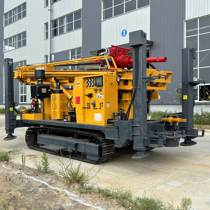
The S in the WR750S model represents a telescopic mast. According to the data, its function is: in transport mode, the mast can improve the overall transport profile and reduce the difficulty of moving between sites; in working mode, it still supports direct operation with 6 m drill pipe and 6 m casing.
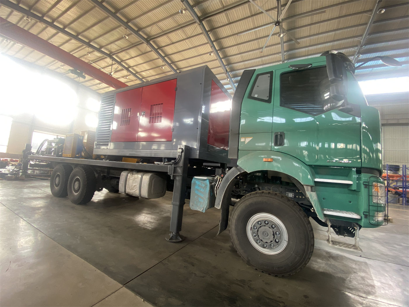
Reading these two statements together makes the value of the telescopic mast clear—it serves compatibility between long drill pipe and transport profile, rather than directly equaling greater drilling depth. If a project is fixed at a few well sites and has low relocation needs, the weight of mast form decreases; conversely, during continuous construction across multiple sites, this structure will repeatedly prove useful. The overall weight is about 14 T, and dimensions are about 6.64 × 2.25 × 2.67 m, indicating that before relocation, flatbed load capacity, road width and height limits must be checked item by item, the telescopic mast must be in a reliably locked state, and 6 m drill pipe and casing should be secured separately.
Rotary configuration: which hole sections do the two torque options apply to?
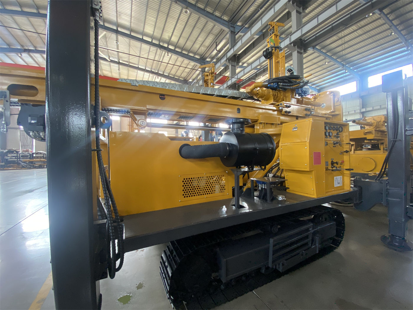
The WR750S rotary system can use either a 13000 / 6500 N·m or 15000 / 7500 N·m configuration, with a maximum rotary speed of 95 / 190 r/min. The data points the larger torque reserve toward large-diameter, hard rock, and high-friction hole sections, and the higher speed toward drilling stages with relatively lower resistance.
One reading that easily arises here is to treat 15,000 N·m as a more comprehensive and better choice than 13,000 N·m. The basis for judgment given in the data is not which is larger, but borehole diameter, drilling tools, and main rock formation—meaning that the same project may have inconsistent torque requirements in different hole sections. The final rotary configuration should be determined based on these three conditions, rather than simply choosing the higher value.
| Comparison item | WR750S data value | Impact on construction stage |
|---|---|---|
| Maximum drilling depth | 750 m | Determines the depth space for sectioning the entire hole |
| Drilling diameter | 105–450 mm | Affects rotary load and casing specifications |
| Lifting force / axial pressure | 40 T / 6 T | Corresponds to drill string handling and deep-hole friction margin |
| Drill pipe | Recommended 102 mm, supports 6 m | Affects number of connections and drill string strength |
| Rotary configuration | 13000 / 6500 or 15000 / 7500 N·m | Selected according to borehole diameter, drilling tools, main rock formation |
| Working air pressure / air consumption | 1.6–6 MPa / 16–75 m³/min | Determines air compressor conditions for DTH hammer matching |
| Overall weight | About 14 T | Constrains relocation transport and platform bearing capacity |
Process conditions: after drilling depth increases, can supporting equipment keep up?
The data recommends a working air pressure of 1.6–6 MPa and air consumption of 16–75 m³/min, compatible with medium- and high-pressure DTH hammers, and specifically notes: if pressure meets requirements but displacement is insufficient, insufficient impact and difficult cuttings removal may still occur. This statement describes one supporting constraint of 750 m class equipment very concretely—air compressor capability cannot be judged by the pressure gauge alone.
Another related statement is: once cuttings removal is poor in a 750 m class deep hole, settled cuttings and repeated crushing will significantly increase torque and energy consumption, so continuous hole cleaning is crucial. Putting these two points together, the requirement that 750 m class equipment places on the air supply system falls on displacement and continuity of hole cleaning, rather than a single pressure value. Under hard rock conditions, attention should also be paid to DTH hammer lubrication and bit wear.
Under what conditions is it necessary to move up to the 750 m class?
The data gives one clear limitation on the number 750 m: 750 m is not a target depth that all projects need to reach, but the maximum reference capability of the equipment. Before formal construction, a more reasonable target horizon should be determined based on regional hydrogeological data. This statement should be read as the starting point for selection.
According to the application description in the data, the WR750S is aimed at scenarios after the scope of deep groundwater construction expands: large groundwater burial depth, unstable shallow aquifers, or projects requiring greater drilling depth margin. In specific projects, this also includes deep agricultural irrigation and large farm water wells, water supply for rural and remote communities with deep groundwater levels, long-term water supply for industrial parks and large infrastructure, and deep water wells in mining areas and some large dewatering boreholes.
If the target aquifer depth has not been confirmed through hydrogeological data, or if the project itself only needs to cover relatively shallow horizons, drilling depth margin will not automatically translate into benefits; instead, it will bring additional burdens in overall weight, relocation, and supporting equipment.
Site entry items easily underestimated under deep-hole conditions
- Crawler travel speed is about 3 km/h, maximum climbing angle reference is 21°, and the overall weight is about 14 T. Before relocation, road and platform bearing capacity should be confirmed, and travel risks in soft soil, slopes, and wet slippery areas must be strictly controlled.
- Hydraulic outrigger stroke is 1.6 m, used for leveling and stabilizing the equipment. Construction at 750 m class takes a long time, so equipment levelness and outrigger settlement control are more critical. Sufficiently large pads should be used on soft ground.
- Auxiliary winch lifting force is 2.5 T, which can be used for moving DTH hammers, drill pipes, casing tools, and site accessories, but rated load and lifting safety requirements must be observed.
- Fast lifting speed is 31 m/min and fast feed speed is 65 m/min, mainly used for drill pipe handling and power head return. In deep-hole projects, the cumulative time of such auxiliary actions will significantly affect effective working time.
- Mud pumps, centrifugal pumps, generators, and foam pumps are optional. The judgment given in the data is that reasonable configuration is more valuable than stacking all accessories: projects with more loose layers rely more on the mud system, hard rock deep holes rely more on high-displacement air compressors and DTH hammers, and formations with severe air leakage may require foam assistance.
Items not covered by the data that need to be confirmed with the manufacturer
The specifications cited in this article all come from published product data for the WR750S. The data does not provide specific lifting force, drill pipe diameter, or torque values for 600 m class models in the same series. Therefore, this article does not draw conclusions about the specific differences between the two classes, but only explains the magnitude of the 750 m class in these fields and the corresponding construction stages.
- The target aquifer horizon and design well depth in the target area need to be determined by hydrogeological data; equipment specifications cannot replace this step.
- Whether the selected air compressor displacement, pressure, and DTH hammer model match the range of 16–75 m³/min and 1.6–6 MPa should be verified with the manufacturer and supporting suppliers.
- Whether the rotary system ultimately uses 13,000 / 6,500 N·m or 15,000 / 7,500 N·m needs to be confirmed in combination with borehole diameter, drilling tools, and main rock formation.
- For filter pipes, water-stop sections, and pump type selection during well completion, the data only mentions that they are as important as the borehole itself, without giving specific plans.
- For the use conditions of casing, foam, or other auxiliary methods in fractured zones, fissures, and air-leakage formations, the data only states that they should be adopted according to conditions, without giving operating procedures.