












A 600-meter deep water well is characterized by a long process, a heavy drill string, and high relocation costs. Once work starts, changing equipment or plans costs far more than during the selection stage. The information to be confirmed before start-up can be grouped into four categories: drill string and lifting load, working states corresponding to hole diameter and formation, site and complete machine support, and air compressor and auxiliary air supply. The following uses the published WR600S parameters as a sample, explaining only what each group checks and which process it constrains; parts not covered by this site's materials are marked separately.
Group 1: Drill String and Lifting Load
For 600-meter-class boreholes, the drill pipe's own weight, thread load, and borehole wall friction all increase with depth, so this group first checks whether the drill pipe specifications and lifting capacity match.
- Maximum drilling depth 600 m, borehole diameter 105–400 mm. These two figures only hold when considered together: the larger the hole diameter, the higher the drill string and cuttings removal load at the same depth.
- Recommended drill pipe diameter 89 / 102 mm, drill pipe length 6 m. Which option to choose is not given in the materials in relation to specific formations and must be confirmed separately based on borehole wall friction and drill tool connection strength.
- Lifting force 35 T, axial pressure 6 T. Deep-hole tripping load is the sum of drill pipe weight, borehole wall friction, and casing weight. The lifting force margin must be calculated according to project conditions; 35 T cannot be directly treated as usable net lifting capacity.
- The S in the model refers to a telescopic mast, allowing the use of 6 m drill pipes during operation to reduce the number of pipe connections; during transport, the telescopic structure improves the overall machine envelope.
- Auxiliary winch lifting force 2.5 T, usable for handling DTH hammers, drill pipes, casing tools, and site accessories.
What needs to be confirmed before start-up in this group is: the planned drill pipe specifications, planned well depth, planned hole diameter, and whether casing operations are involved. The materials mention that if tripping resistance is abnormal, the hole should first be cleaned and the borehole wall condition assessed, rather than directly relying on maximum lifting force to handle it—this is an operational reminder given in the equipment materials, and the specific handling method should still be determined by the on-site technical plan.
Group 2: Working States Corresponding to Hole Diameter and Formation
The rotary system provides dual-condition values: maximum torque 12000 / 6000 N·m, corresponding to maximum rotation speed 90 / 180 r/min. The low-speed, high-torque state is suitable for larger hole diameters, hard rock, and high-friction hole sections; when resistance is lower or the drill tool load is lighter, a higher rotation speed can be selected. Actual construction should be dynamically adjusted according to the drill bit, DTH hammer, cuttings return, and rotary load.
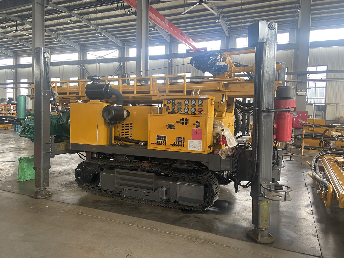
Before start-up, the formation sections corresponding to the borehole design must be listed, and then it must be determined which hole sections fall into which working state. Three things must not be mixed up: the hole diameter range 105–400 mm is the equipment capability range, not the planned hole diameter of a specific project; 12000 N·m and 6000 N·m are values for two working conditions, not speed options for two gears; the reference drilling efficiency of 10–35 m/h is a reference value given in the materials, and actual penetration depends on formation hardness, hole diameter, DTH hammer, air compressor displacement, and operating method.
Recommended working air pressure for DTH drilling is 1.2–3.5 MPa, with air consumption 16–55 m³/min. After entering relatively intact hard rock, medium- and high-pressure DTH hammers can be used; weathered rock and alternating soft-hard formations drill faster but the borehole wall is prone to block falling and diameter reduction; upper soil layers, clay, sand layers, and gravel layers support mud rotary drilling, and priority should be given to hole stabilization, cuttings carrying, and borehole wall protection. After entering the main aquifer, groundwater will change the cuttings removal and downhole pressure state, and the depth of the main water-producing layer must be recorded.
Group 3: Site and Complete Machine Support
This group of conditions determines whether the equipment can be put in place and whether it can remain stable once in place.
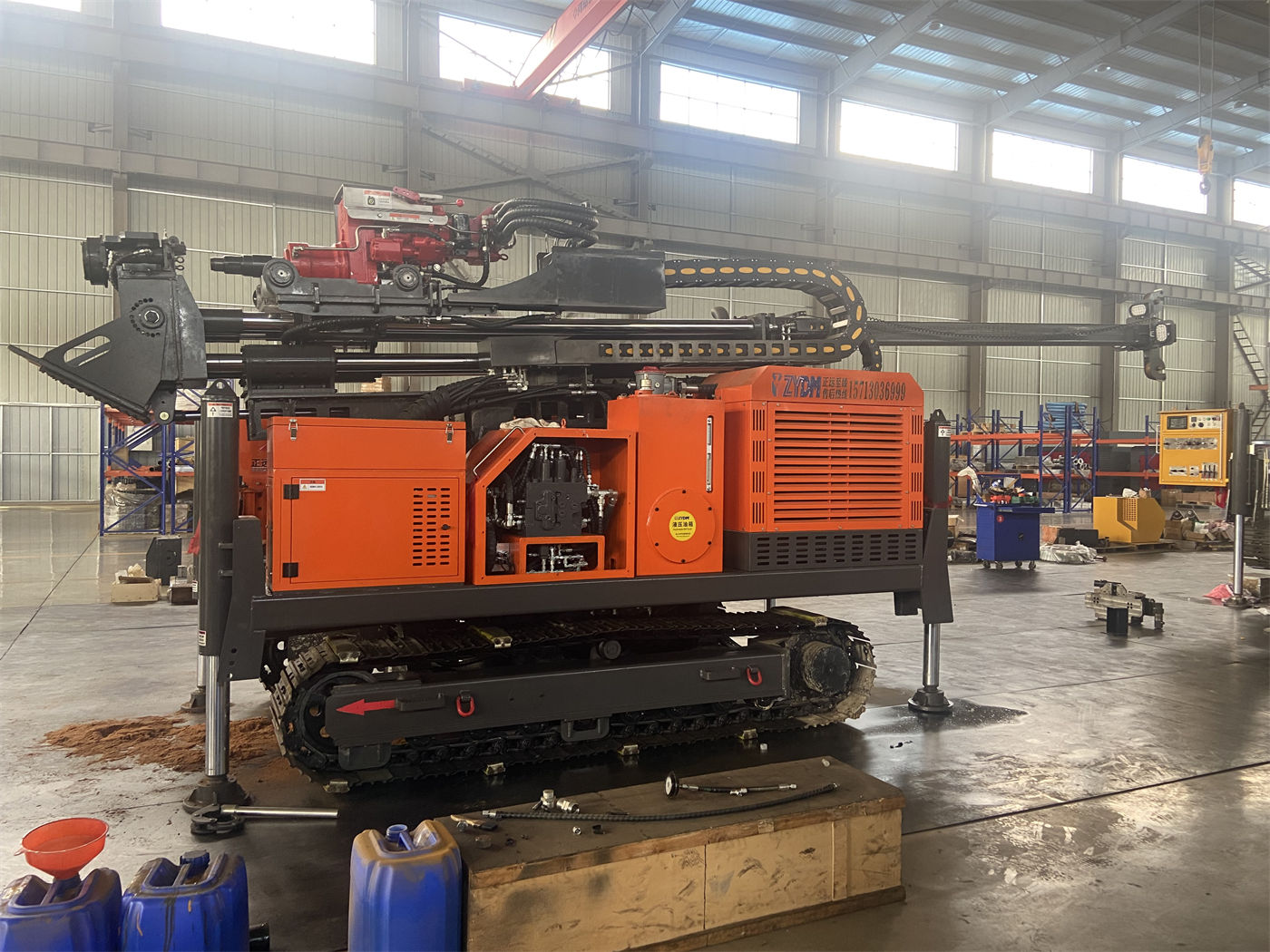
- The complete machine weighs about 12.5 T, with overall dimensions about 6.73 × 2.1 × 2.63 m. Transport requires arranging a flatbed truck according to vehicle load capacity and road width and height limits, and checking the telescopic mast lock and equipment fixing points.
- Crawler travel speed is about 3 km/h, with a maximum climbing angle reference of 21°. The materials also note that before relocation, ground bearing capacity, slope, and wet or slippery conditions should be confirmed, and direct high-load travel on soft ground should be avoided.
- Hydraulic outrigger stroke 1.6 m, used for equipment leveling and stable support. A 600-meter-class borehole has a long construction time, and complete machine stability directly affects mast stress; pads should be used on soft ground. The specific pad specifications and foundation treatment methods are not given in the materials.
- After arriving at the site, sufficient space for mast deployment must be reserved. This is a site condition along with transport dimensions, but the operating footprint envelope is not listed in the materials.
What needs to be confirmed before start-up is: road access conditions from the highway to the hole location, the size of the parking surface around the hole location, ground bearing conditions, and relocation distance between multiple wells. These must all be verified according to the actual site and cannot be directly inferred from the complete machine dimensions and climbing angle.
Group 4: Air Compressor and Auxiliary Air Supply
In 600-meter-class deep holes, compressed air simultaneously handles impact and downhole cuttings removal. The air consumption range given in the materials is 16–55 m³/min and working pressure 1.2–3.5 MPa, with an explicit note: as hole depth increases, hole diameter increases, rock layers harden, or altitude rises, the actual required displacement may increase, so the air compressor must be matched separately for each project.
Other auxiliary equipment in the same group also includes mud pumps, centrifugal pumps, generators, and foam pumps (described in the materials as optional configurations). What needs to be confirmed before start-up is: the air compressor displacement and pressure corresponding to the selected process route, whether one unit or multiple units in parallel, the length of the air supply pipeline, and whether the upper overburden requires the mud system to be present at the same time. The specific air compressor model and quantity are not given in this site's materials and should be confirmed with the manufacturer or according to the project design.
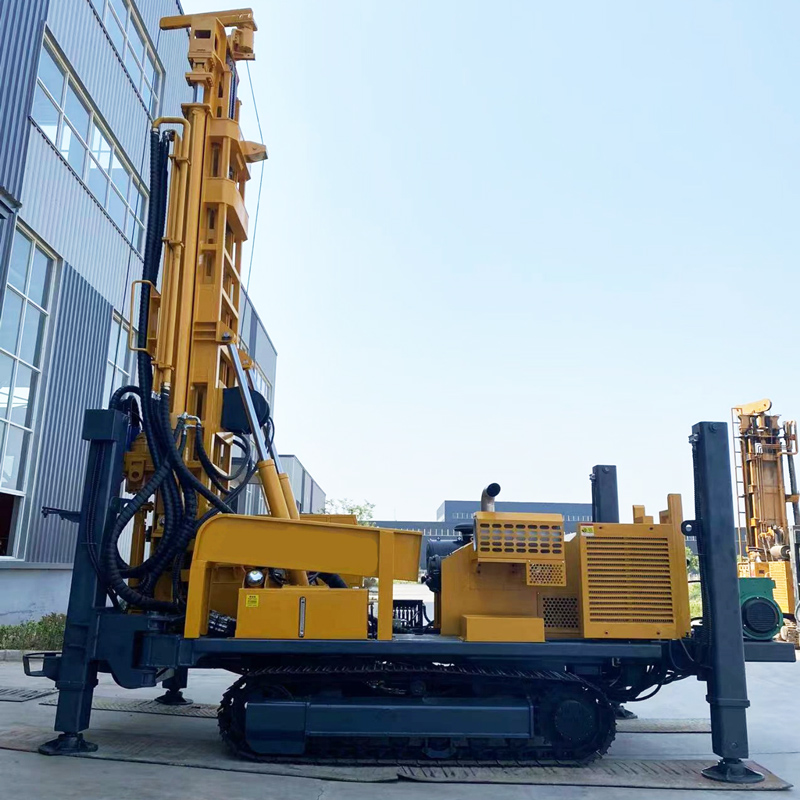
In addition, the 132 kW Cummins engine provides power for rotation, feed, crawler travel, and auxiliary hydraulic systems. For projects with high dust, the materials note that radiator and filter cleaning frequency should be increased.
Correspondence Between the Four Condition Groups and Their Processes
| Condition Group | Main Check Items | Constrained Process |
|---|---|---|
| Drill string and lifting load | Drill pipe diameter and length, 35 T lifting force, 6 T axial pressure | Tripping, pipe connection, possible casing operations |
| Hole diameter and formation | 12000/6000 N·m, 90/180 r/min, 1.2–3.5 MPa | Hard rock, alternating soft-hard, overburden and aquifer hole sections |
| Site and support | 12.5 T complete machine, 6.73×2.1×2.63 m, 1.6 m outriggers | Transport entry, positioning, mast deployment |
| Auxiliary air supply | 16–55 m³/min air consumption, optional pumps and generator | DTH drilling and cuttings removal, upper overburden treatment |
Parts Not Covered by the Materials and Requiring Separate Confirmation
The following items have no corresponding values or conclusions in this site's materials: how to determine the completed well depth under the specific hydrogeological conditions of the well location; which torque setting is more suitable for a planned hole diameter within the 95 to 400 mm range; the specific start-stop sequence when switching between mud positive circulation and DTH; the air compressor model, quantity, and air supply pipeline configuration; and the pad specifications and foundation treatment methods for soft ground. These should be confirmed before start-up by the project technical plan or with the manufacturer; this article does not provide inferred conclusions.