












Between the well depth requirement and the mast type of a water well drilling rig lies a series of judgments that need to be settled in sequence. The product information for the WR500S contains several figures at the same time: maximum drilling depth 500 m, 6 m drill pipe, telescopic mast, overall weight about 10.6 T, and dimensions about 6.52 × 1.85 × 2.51 m. These figures are not parallel; they have a sequential relationship—which item is determined first decides the range within which the later items can be selected. This article follows that order and relies only on the product information already published on this site. Parts not covered by the data are explained separately.
Step 1: Target well depth is not equal to the equipment's maximum drilling depth
The maximum drilling depth stated in the WR500S information is 500 m, with a drilling diameter of 105–400 mm. But the same information also notes that a 500-meter-class depth does not mean every well must be drilled to 500 meters; the final well depth should be determined according to local hydrogeology and the position of the water-bearing layer. This information is placed first in the judgment sequence because it determines the question of "whether to enter the 500-meter class," not "which mast to choose."
In this step, two types of depth need to be separated first: the target completed well depth, and the depth margin reserved for dealing with formation changes and uncertainty in aquifer position. Together they determine the lower limit of the equipment's drilling depth capability, but neither directly points to the mast structure. If the actual completed well depth of the project is stably in a shallower range, then whether the remaining capabilities of 500-meter-class equipment are still necessary needs to be judged together with the later conditions.
Step 2: Drill pipe length and pipe connection method
According to the information on this site, the WR500S supports 6 m drill pipes, with a recommended drill pipe diameter of 89 mm. The reason drill pipe length comes before mast type is that it directly affects the number of pipe connections per well, and therefore the proportion of auxiliary time. The WR500S information clearly states that for 500-meter-class hole depths, reducing the number of pipe connections can significantly lower auxiliary time.
Drill pipe length also brings out two parameters here. One is the effective height after the mast is deployed—a 6 m drill pipe must be run in and pulled out within the mast, so the mast height must match it. The other is the auxiliary winch. In the information, the auxiliary winch lifting force of the WR500S is 1.5 T, which can be used for handling DTH hammers, drill pipes, casing tools, and other accessories; when using 6 m drill pipes, the lifting points and manual guidance need to be reasonably set to avoid lateral swinging of the drill pipe and collision with the mast.
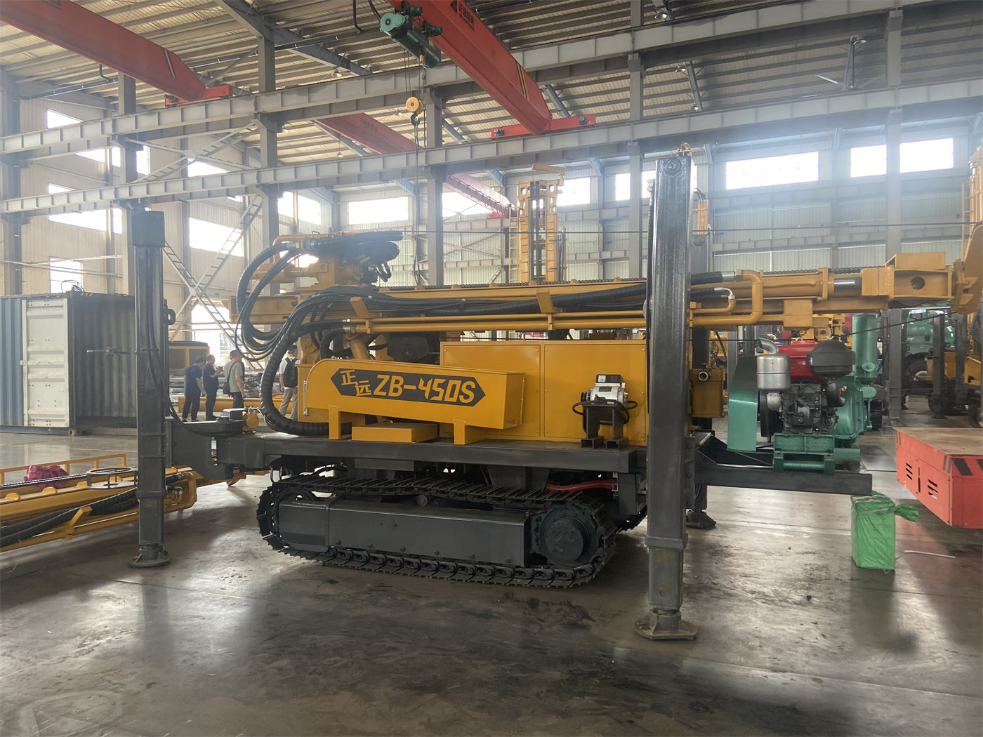
Therefore, in this step, what needs to be confirmed is: how long a drill pipe the project plans to use, and whether this length is compatible with the mast deployment height and run-in/pull-out method of the intended model.
Step 3: Trade-offs in mast type
Mast type is placed in step three because it is constrained by the first two steps at the same time. The WR500S uses a telescopic mast structure. The information on the telescopic mast focuses on two states: transport and construction. In the transport state, the equipment's outer dimensions can be shortened, which facilitates loading, road passage, and cross-project relocation; after arriving at the site and deploying the mast, it can support continuous construction with 6 m drill pipes.
What this passage implies is a trade-off relationship. Supporting 6 m drill pipes means that after the mast is deployed, sufficient height is required; a fixed long mast also satisfies this item, but it changes the outer dimensions in the transport state. The telescopic structure handles these two states separately. To judge whether a project is suitable, both ends need to be considered at the same time: whether the site needs the reduction in pipe connections brought by 6 m drill pipes, and whether the equipment needs to be frequently moved between work sites and whether there are restrictions on road passability along the way.
Also directly related to transport in the information are the overall weight and dimensions: overall weight about 10.6 T, dimensions about 6.52 × 1.85 × 2.51 m. During transport, a flatbed truck should be arranged according to vehicle load, road width limits, and height limits, and the telescopic mast locking, equipment fixing points, and drill pipe bundling status should be checked. After arriving at the site, sufficient space for mast deployment should also be reserved. These items are implementation work after the mast type is selected and do not change the preceding judgment sequence.
Step 4: Return to checking load and rotary capability
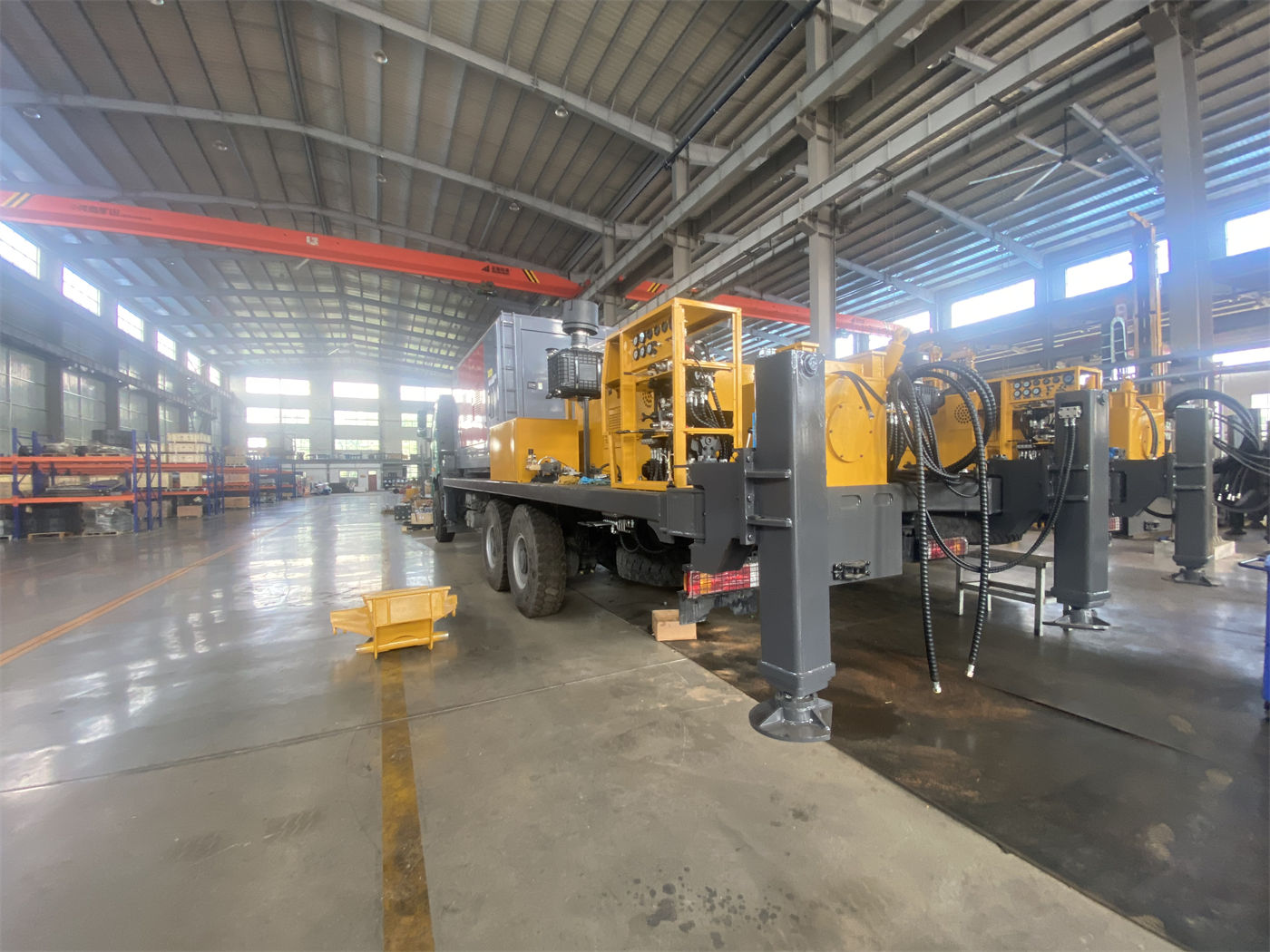
Only after the mast type is determined can the parameter check directly related to the drilling process begin. The data given for the WR500S in the information on this site are as follows:
| Parameter | Value |
|---|---|
| Maximum drilling depth | 500 m |
| Drilling diameter | 105–400 mm |
| Lifting force | 30 T |
| Rotary torque | 11000 / 5500 N·m |
| Maximum rotary speed | 75 / 150 r/min |
| Reference axial pressure | 6 T |
| Fast feed / fast lift speed | 48 m/min / 29 m/min |
| Auxiliary winch lifting force | 1.5 T |
| Engine power | 110 kW (Yuchai) |
The lifting force item is most directly related to drilling depth. The information explains that at 500-meter-class hole depths, the self-weight of the drill pipe, borehole wall friction, and casing weight all increase significantly, and a 30 T lifting force is beneficial for normal tripping, DTH hammer recovery, and some casing operations. The information also notes that if abnormal pulling resistance occurs, the hole should first be cleaned and the condition of the borehole wall and drilling tools judged, rather than directly using the maximum lifting force to force handling.
The rotary part has two working conditions: 11000 / 5500 N·m corresponding to 75 / 150 r/min. The explanation given in the information is that the low-speed high-torque condition is suitable for large diameters, hard rock, and relatively high loads, while the higher-speed condition is suitable for drilling stages with relatively low resistance. On site, rotary parameters should be adjusted according to hole diameter, DTH hammer, and return cuttings status. The 6 T axial pressure is used to control drill tool feed, while fast feed and fast lift mainly serve power head movement and drill pipe handling. The information also clearly states that actual penetration efficiency in rock formations is still affected by lithology, bit, air compressor, and operating method.
Step 5: Process route and air supply support
The WR500S supports DTH down-the-hole drilling and mud rotary drilling. The information mentions that the process can be switched according to the conditions of the upper loose layer and the lower rock layer. The air supply conditions related to DTH are given separately: recommended working pressure 1.2–3.5 MPa, air consumption 16–55 m³/min. The information also explains that when the hole diameter increases, the rock formation becomes harder, the hole depth increases, or the altitude rises, the requirement for air compressor displacement will be higher. Air compressor selection should consider both pressure and flow, not just a single pressure indicator.
At the process route level, the information distinguishes the prerequisites for handling several types of formations:
- Intact rock formations (granite, limestone, sandstone, etc.): medium- and high-pressure DTH hammers with matching bits can be used; when drilling hard rock, DTH hammer lubrication, sufficient air volume, and continuous cuttings removal must be ensured.
- Weathered rock and alternating soft-hard formations: parameters should be adjusted in a timely manner according to rotary torque and feed resistance; when the upper weathered layer is thick, casing or mud can be used to stabilize the hole.
- Soil, clay, sand, and gravel overburden: a stable hole section can be established through mud circulation, casing, or other hole stabilization measures, and then DTH can be switched to after entering the rock formation.
- Fracture zones, fissures, and air-leakage formations: the information notes that these may cause block falling, air leakage, sticking, and abnormal cuttings return. Excessive fast feed should be reduced, continuous hole cleaning should be maintained, and foam or casing should be used according to site conditions; if air loss is obvious, it should be judged whether large fissures or cavities exist, rather than only increasing air compressor pressure.
- Aquifers and strong water inflow conditions: after entering the main aquifer, groundwater will change the return cuttings in the hole and the working state of the DTH hammer. The depth of the aquifer should be recorded in a timely manner, and air supply, hole cleaning, and casing methods should be adjusted according to the water inflow.
The information also lists the range of optional accessories: mud pump, centrifugal pump, generator, and foam pump. Projects with more loose layers place more emphasis on the mud system, hard rock projects rely more on air compressors and DTH hammers, and formations with severe air leakage may require foam assistance. The information does not provide a selection table matching these accessories to specific working conditions.
Step 6: Site, support, and travel conditions
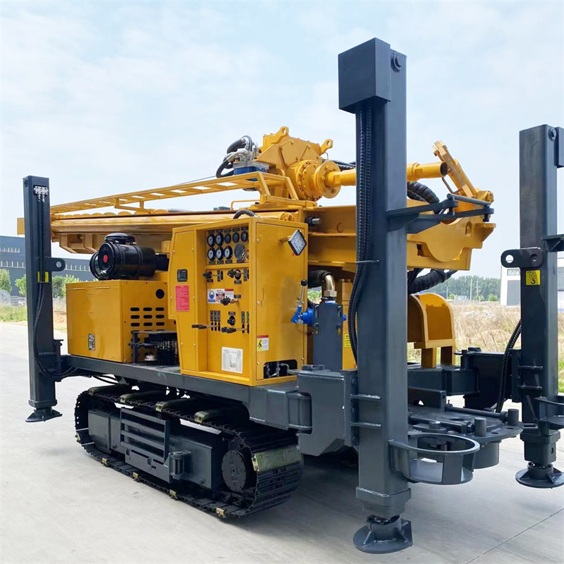
The final step checks the match between the equipment and the site. The relevant data for the WR500S in the information on this site are: crawler travel speed about 3 km/h, maximum climbing angle reference 21°, hydraulic outrigger stroke 1.6 m. The information explains that the crawler structure is suitable for gravel roads in mining areas, rural roads, and general uneven sites; because the overall weight is about 10.6 T, during relocation, ground bearing capacity, slope, and wet/slippery conditions should be confirmed with emphasis.
The outrigger item is related to the stability of 500-meter-class operations. The information mentions that 500-meter-class water well construction has a relatively long cycle, and the level state of the equipment affects mast stress and hole deviation control; on soft ground, pads should be added to avoid settlement after long-term stress on the outriggers. In addition, daily inspections should focus on the telescopic mast guide rails, cylinders, pins, and locking structures; when using 6 m drill pipes, the mast should be fully deployed and reliably fixed.
Parts not answered by the data in this judgment sequence
After following the above sequence, there are still several types of information outside the scope of the data published on this site, and no conclusions can be given based on them:
- Hydrogeological data, aquifer depth, and expected water yield for the specific project location belong to project-side data and need to be provided by the project party.
- The specific design of well casing size, submersible pump specifications, and completed well body structure. The information only mentions in the well completion section that the hole diameter and well body structure should be designed according to expected water yield, well casing size, and submersible pump specifications, without giving specific numerical correspondences.
- The specific matching models and displacement combinations of air compressors and the main machine. The information only gives the recommended pressure and air consumption range, as well as the directional explanation that displacement requirements will increase under different conditions.
- Actual penetration efficiency under different formations. The information clearly states that it is affected by lithology, bit, air compressor, and operating method, and is subject to on-site working conditions.
These types of information determine whether the well depth requirement can truly be implemented, but they are not within the scope that an equipment parameter table can answer and need to be verified separately during the selection confirmation stage.