












In the WR450SE information, the 20 T lifting force is listed alongside several numbers: maximum drilling depth 450 m, 6 m drill pipe, recommended drill pipe diameter 89 / 102 mm, fast lifting speed 30 m/min, auxiliary winch 1.1 T (optional 2.5 T). Unlike drilling depth, the lifting force column does not directly correspond to a project goal; it is more like an intermediate quantity—connected above to drill string weight and below to tripping, casing, and downhole anomaly handling. This article only looks at what this single value is used to support at 450-meter-class hole depth, and which parts lack quantitative conclusions in the available information.
First, distinguish: lifting force is not the same as drilling capability
Lifting force describes how heavy a drill string assembly the hoisting system can lift, while rotary torque describes how heavy a tool the drill string can drive at the bottom of the hole; the two act in different directions downhole. The maximum rotary torque given for the WR450SE is 9000 / 4500 N·m, corresponding to maximum rotary speeds of 90 / 180 r/min. Viewing lifting force and torque as one combined number would mistakenly suggest that the two can be interconverted—the information does not provide such a conversion relationship.
Another easily confused point is that the 20 T lifting force is not the maximum weight this equipment can pull. The drill string in the hole, borehole wall friction, whether casing is present, and whether the string is stuck will all cause the actual load to be overcome to deviate from the net weight of the drill tools. The information positions the 20 T lifting force as "meeting 450-meter-class conventional drill pipe tripping, DTH hammer recovery, and some casing operations"; this is a statement of usage conditions, not a quantitative promise of load margin.
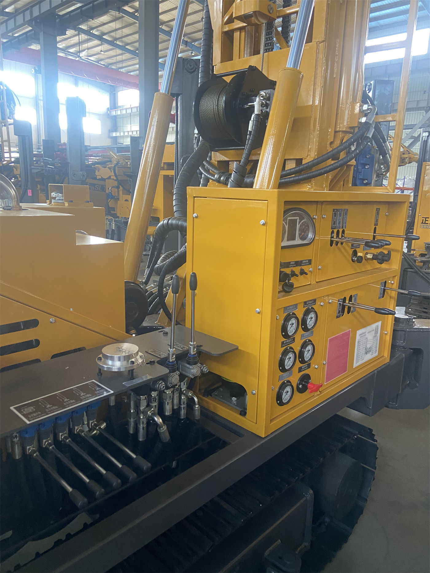
The closer the drill pipe is to the next joint, the more the load increases upward
For a 450 m hole depth with 6 m drill pipes, the theoretical number of drill pipes required is determined by dividing hole depth by the length of a single pipe; as borehole diameter increases, the weight per unit length of drill pipe also changes. The information recommends two drill pipe diameters, 89 mm and 102 mm, but does not separately give the corresponding total drill string weight at any hole depth. Therefore, when designing a specific well, the drill pipe length, diameter, and number of joints need to be calculated separately according to the actual drill pipe specifications selected, and the calculation results should then be checked against the 20 T lifting force to see whether they fall within a reasonable range.
As hole depth increases, there are two additional loads not included in the net weight of the drill tools: first, borehole wall friction; second, drill cuttings that may remain above the bottomhole tool during pull-out. In the description of fractured zones, the information mentions block falling, air leakage, and sticking; in the description of aquifers, it mentions that water inflow will change downhole working conditions. These occur separately from the 20 T lifting force and cannot be used directly to infer "how deep it can lift" from the lifting force value.
Beyond lifting force, the same operation also has three supporting items
| Parameter item | Information value | Operation in which it appears |
|---|---|---|
| Fast lifting speed | 30 m/min | Auxiliary actions such as power head return and drill pipe handling |
| Fast feed speed | 55 m/min | Same as above, opposite direction |
| Auxiliary winch lifting force | 1.1 T (2.5 T optional) | Drill tool handling; optional upgrade for projects with heavy attachments |
| Hydraulic outrigger stroke | 1.6 m | Leveling and support |
Fast lifting speed is easily understood as pull-out speed, but the information states it is "used for power head return, drill pipe handling, and other auxiliary actions, can reduce non-drilling time, but cannot directly represent the actual penetration rate in rock formations." This sentence limits the use of the 30 m/min value to auxiliary actions; when reading it, do not extend it to drilling efficiency.
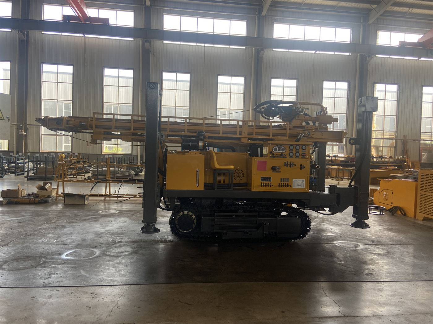
The auxiliary winch's 1.1 T and the main hoist's 20 T are two systems, and their objects of action are also different: the main hoist corresponds to the downhole drill string, while the auxiliary winch corresponds to surface drill tool handling. The information mentions that when DTH hammers, casing, or other attachments are relatively heavy in a project, upgrading to the 2.5 T configuration can be considered.
The correspondence between lifting force and hole diameter or formation is not given in the information
The WR450SE borehole diameter range is 105–400 mm. The information maps borehole diameter, rotary torque, and air pressure to different working states: large-diameter, hard rock, or high-resistance hole sections use the low-speed high-torque gear; stages with relatively low resistance use the high-speed gear; for pneumatic DTH drilling, the recommended working air pressure is 1.2–3.5 MPa, with air consumption of 16–55 m³/min. These three parameter groups each have their own correspondences, but the information does not provide a conversion table for "how long a drill string the 20 T lifting force can lift at a given borehole diameter," nor does it list the lifting force requirements for casing operations at different borehole diameters.
When actually designing a well, it is necessary to supplement information such as well diameter, specifications of the drill tools and casing to be run, and expected downhole friction, and then judge whether the 20 T lifting force has margin. The statement in the information that "after hole depth increases, both drill pipe self-weight and borehole wall friction will rise; therefore, when abnormal pull-out resistance is encountered, first judge the borehole wall, cuttings removal, and drill tool condition, then take measures such as hole cleaning, slow lifting, or casing" can be used to determine the direction of handling under abnormal conditions, but it does not constitute safe operating steps.
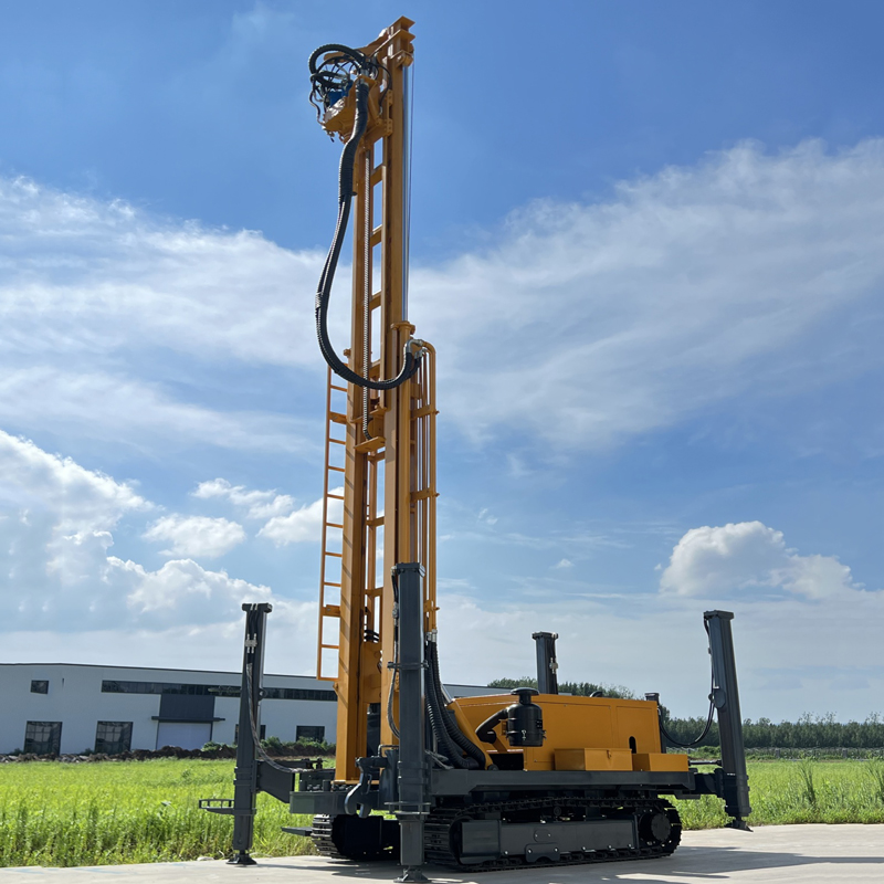
Putting lifting force back into the overall machine conditions
The 20 T lifting force is matched with a 92 kW power system, an overall machine weight of about 8.5 T, overall dimensions of about 5.85 × 1.8 × 2.4 m, a travel speed of about 2.5 km/h, and a maximum climbing angle reference of 21°. These parameters respectively constrain power, relocation, and site adaptability, and have no conversion relationship with the lifting force itself, but together they determine the overall conditions under which this equipment handles 450-meter-class hole depth. On soft ground, pads should be used to prevent outrigger settlement; before relocation, ground bearing capacity and slope conditions should be confirmed. These are all explicit reminders in the information.
The final paragraph of the information states: because actual geological conditions, downhole tools, drilling angle, and operating methods differ, the final drilling efficiency, drilling depth, and well completion effect should be based on on-site working conditions. The same sentence also applies to the 20 T lifting force—it provides the lifting capacity for 450-meter-class conventional operations, but for the drill string assembly and casing arrangement of a specific well, separate calculation is still required at the design stage. The conversion and method parts not covered by the information need to be confirmed with the manufacturer or engineering technical personnel before use.