












In the WR400S documentation, there is a rather inconspicuous statement: it supports direct operation with 6-meter drill pipe and 6-meter casing. Many selection discussions directly convert "6 meters" into mast height and then end the judgment. However, this statement appears in both the drill pipe and casing columns, pointing to two different stages of operations, and the casing column is especially prone to simplification.
First, clarify the question
"Directly running 6-meter casing" in the WR400S documentation describes an operating method: when the single casing segment length is 6 m, there is no need to first cut it shorter or split it into shorter segments and connect them one by one; the equipment's mast height, lifting capacity, and operating space can accommodate this length segment.
It does not directly explain the following: casing specifications and wall thickness, borehole wall conditions during casing running, whether specialized lifting tools are needed, and how filter pipes and sealing sections are arranged after well completion. These are not provided in the documentation and need to be confirmed separately according to specific projects.
The 6-meter length is written in both columns, but it does not point to the same operation
The 6 meters in the drill pipe column applies to the drilling stage—reducing the number of pipe connections in 300–400-meter-class hole depths, lowering auxiliary time and manual handling frequency. This layer is explicitly stated in the documentation.
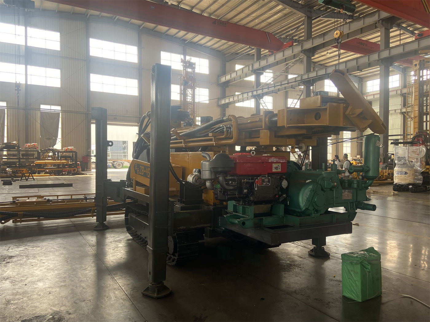
The 6 meters in the casing column applies to the well completion stage. Casing is not a drilling tool; after being run into the hole, it is not removed and typically serves functions of wall protection, isolation, and water filtration. The only similarity between the two stages is that "both are 6-meter segments." The difference is that drill pipe must be repeatedly connected and disconnected, while casing is generally run in only once, and when it is run in, the borehole wall conditions and hole diameter state are already different from those during drilling.
Where does the casing running step fit in the well completion process
According to the general sequence of water well completion, the casing running stage begins only after drilling is completed and the hole is cleaned. This means that the room for adjustment at this point is smaller than during drilling: the hole has already taken shape, and if diameter reduction, block falling, or bottom-hole debris accumulation occurs, the cost escalation is faster than during the drilling stage.
Therefore, "whether 6-meter casing can be directly run" essentially asks whether three things can hold true simultaneously: whether the mast and operating space can accommodate this length segment; whether the lifting and auxiliary mechanisms can smoothly send it into the hole; and whether the in-hole conditions are stable during this single run. The first two have corresponding figures in the documentation, while the third is determined by formation and hole cleaning quality and is outside the scope of the equipment parameter table.
Two conditions that can be matched in the documentation
- Lifting force 22 T, axial pressure 4 T. The casing itself has weight, and during running it may also encounter borehole wall friction. Whether the lifting capacity has margin should be calculated according to actual casing specifications and hole depth; the documentation does not provide a corresponding table.
- Auxiliary winch lifting force 1.5 T, which can be used for handling drill pipe, casing tools, and on-site accessories. The value of this item is not on the same order of magnitude as casing weight, and the actual lifting method needs to be determined according to on-site configuration.
Several parameters related to casing operations should be viewed together
| Parameter | Value | Relationship to casing operations |
|---|---|---|
| Maximum drilling depth | 400 m | Determines the order of magnitude of total casing length, not single-segment length |
| Drilling diameter | 105–325 mm | Casing outer diameter must fall within the hole diameter range; specific matching is not listed in the documentation |
| Lifting force | 22 T | Bears casing dead weight and running resistance |
| Auxiliary winch | 1.5 T | Used for accessory handling, not equal to casing lifting capacity |
| Mast type | Telescopic mast | Supports direct operation with 6 m drill pipe or casing in working condition |
The hole diameter in the table is the drilling range, not the casing specification range. The two need to be converted according to well completion design. The documentation on this site does not provide the corresponding relationship, and it should be verified with the supplier before ordering equipment.
The role of the telescopic mast here
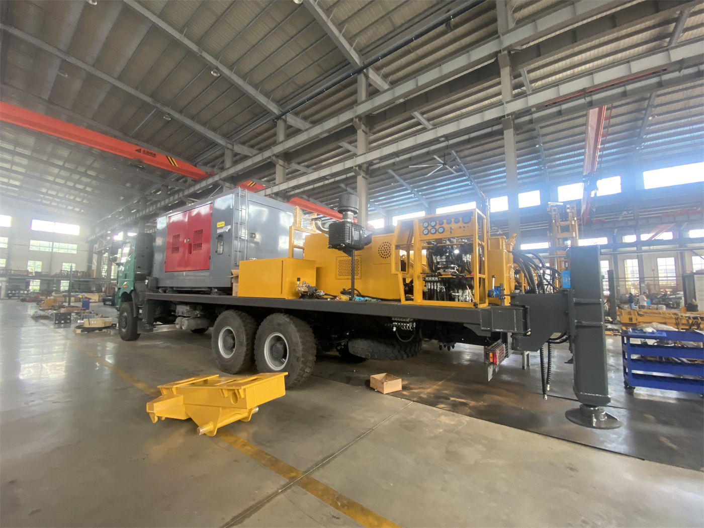
The S in the WR400S model represents a telescopic mast. The documentation describes it mainly in terms of the balance between transport and operation: during relocation, the mast can be shortened to reduce the transport profile, lowering loading and road passage difficulty; after arriving at the hole location, it is extended to continue maintaining direct operation capability with 6 m drill pipe or casing.
It is necessary to distinguish: the telescopic mast changes the overall machine profile in transport condition, not the single-segment length in working condition. The overall weight is about 9.8 T, and the overall dimensions are about 6.26 × 1.85 × 2.43 m. Whether these two values correspond to transport condition or working condition is not individually marked in the documentation and is a matter requiring confirmation.
In which cases does the 6-meter casing segment length not constitute a constraint
If the project itself designs casing according to shorter segments, or if the well completion process uses other casing running methods, then the 6-meter item will not become a selection condition, and equipment trade-offs should return to drilling depth, hole diameter, formation, and air supply capacity.
Conversely, only when the project procures casing in 6-meter segments and hopes to reduce downhole pipe connection frequency does this item truly enter the judgment. The documentation does not state whether 6 meters is the upper limit of casing length for this model, nor does it explain the adaptability of shorter segments. These two points need separate confirmation.
Process conditions that hold simultaneously with long casing operations
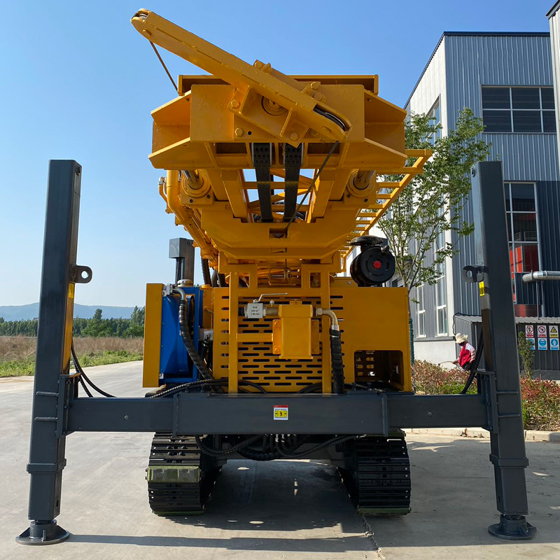
The documentation shows that the WR400S supports two paths: mud drilling and down-the-hole hammer drilling. For loose overburden such as soil, clay, and sand layers, mud circulation can be used for wall protection and cuttings carrying; for relatively intact hard rock, down-the-hole hammer pneumatic drilling can be used, with recommended working air pressure of 1.2–3.5 MPa and air consumption of 16–55 m³/min.
For casing running, the hole-forming stability of the upper loose layer is more critical. The documentation mentions that when the upper unstable hole section is thick, follow-up casing can be considered to reduce borehole wall problems in the deep hole stage. Follow-up casing and post-completion casing running are two different methods, and the documentation does not elaborate on their respective applicable conditions.
Matters not answered by the documentation and requiring confirmation
- The adaptability range of the 6-meter length to different casing outer diameters and wall thicknesses;
- The correspondence between total casing weight and 22 T lifting force, and whether friction margin is included;
- Whether specialized lifting tools, centralizers, or guide devices are needed during casing running;
- Which set of values corresponds to the dimensions and weight of the telescopic mast in working condition and transport condition, respectively.
These questions cannot be concluded from existing parameters and belong to items that should be verified one by one with the supplier during the selection and contract confirmation stage. Using "able to directly run 6-meter casing" as a conclusion presupposes clarifying the above items together.