












The difficulty of continuous irrigation well construction usually lies not in the depth of a single well, but in the number of repetitions. The same equipment must complete multiple wells within one irrigation season. Each well must go through the procedures of positioning, opening, completion, well washing, and moving again, and auxiliary time is repeatedly accumulated. Therefore, judging whether a piece of equipment can handle such tasks depends not only on maximum drilling depth, but on whether its capabilities are sufficient and whether switching is smooth under conditions of "multiple wells, scattered well locations, and inconsistent formations."
The following uses the WR350SE parameters published on this site as a sample. It is a 350-meter-class crawler water well drilling rig, with a drilling diameter of 105–350 mm, supporting 3-meter and 6-meter drill rods, equipped with 91 kW power, 16 T lifting force, 8500 / 4250 N·m dual-condition torque, and a total weight of about 7.5 T. Only these existing values and descriptions are used below; parts not covered by the data are separately marked as to be confirmed.
Condition 1: Drilling depth and hole diameter should cover the well type, not the equipment limit
The maximum drilling depth of the WR350SE is 350 m, and the drilling diameter is 105–350 mm. The data also states: for irrigation wells, the final well diameter and well depth should be determined based on aquifer burial depth, planned water output, and pump type, rather than simply constructing according to the equipment's maximum capability. This statement is especially important for continuous construction—if multiple wells have inconsistent depths and diameters, the equipment needs to switch back and forth between different working states rather than drilling to the end with one fixed parameter.
Information that needs to be confirmed well by well includes: aquifer burial depth, designed water output, outer diameter of the submersible pump to be used, and pump installation depth. These data determine the completed hole diameter and final hole depth of each well, and also determine filter arrangement and the position of the sealing section.
Condition 2: 3-meter and 6-meter drill rods affect the number of rod connections
The WR350SE supports 3 m and 6 m drill rods, with recommended drill rod diameters of 89 / 102 mm. The data explains this point as follows: 3-meter drill rods are more suitable for projects with ordinary transportation conditions and limited construction sites; 6-meter drill rods can reduce the number of rod connections and improve continuous drilling efficiency. For construction teams that need to complete longer footage within one day, reducing the time for adding and removing drill rods can directly improve effective equipment utilization.
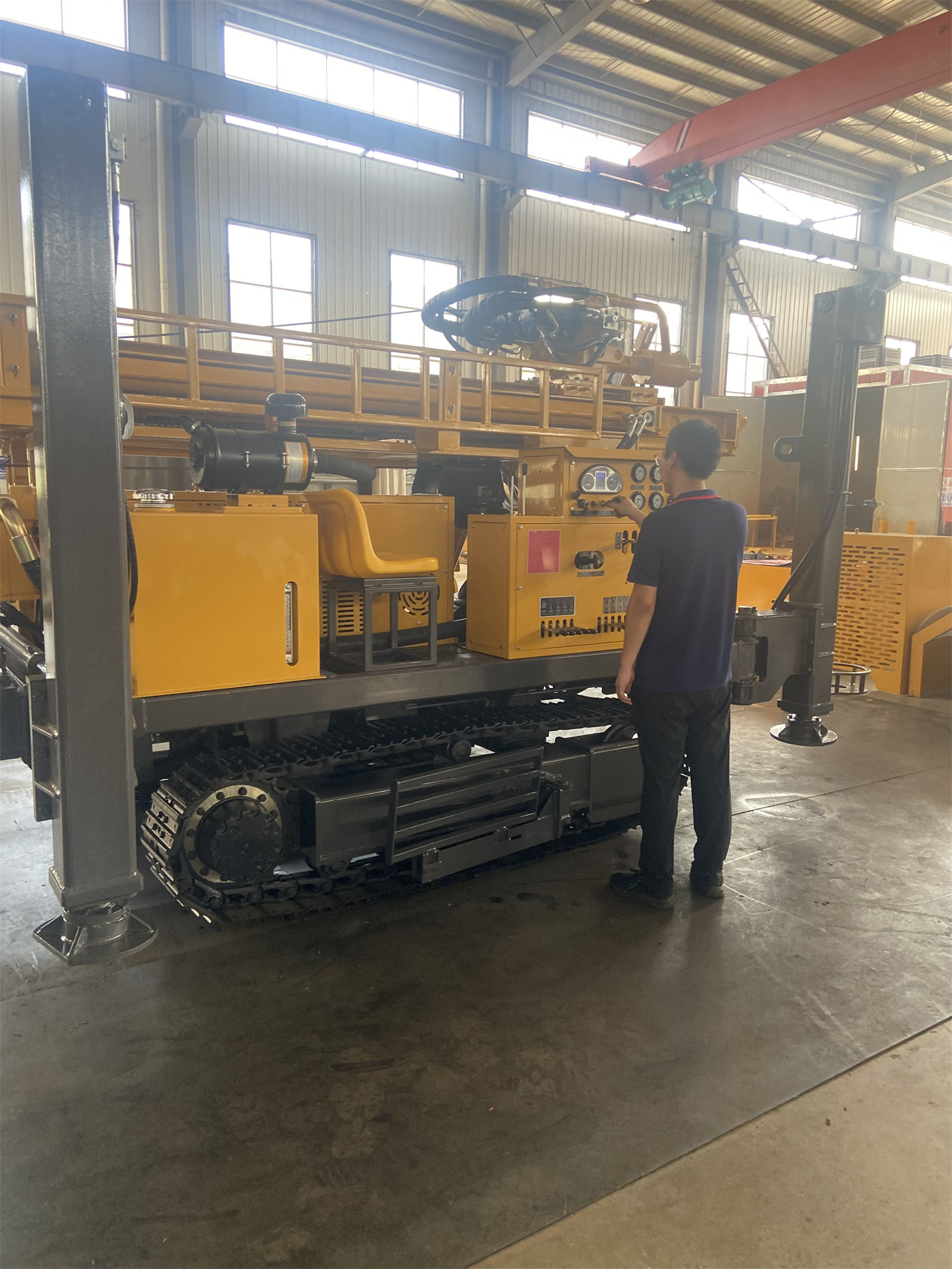
Looking at this item in a continuous construction scenario, it corresponds to the rod connection action that is repeatedly performed for each well. The longer the drill rod, the fewer rod connections within a single hole, and the shorter the total time of repeated procedures; but longer drill rods also place higher requirements on tower height, transportation length, and site clearance. How to balance these two ends depends on the road conditions and site size between well locations.
Condition 3: Two sets of processes should be prepared for loose formations and rock layers
The data clearly states that the WR350SE is suitable for loose formations and rock layers, and gives a staged approach: the upper soil layer, clay, sand layer, and gravel layer can use mud rotary, casing, or other hole stabilization methods; after entering weathered rock and intact rock layers, it can switch to DTH hammer drilling. For continuous construction, this means that the same equipment may need to use two sets of processes in the same well, and the switching timing and preparation materials need to be arranged in advance.
The data also notes two formation states that require attention: weathered rock usually has faster footage, but is prone to block falling and hole shrinkage. When encountering alternating soft and hard formations, attention should be paid to changes in rotary torque, feed resistance, and cuttings return; fractured and broken formations may cause air leakage, block falling, sticking, and abnormal cuttings discharge. Rapid forced pushing should be avoided, and foam, casing, or other auxiliary measures can be used according to site conditions. When the upper unstable hole section is thick, casing configuration should be considered in advance.
Condition 4: Air supply configuration should change according to hole diameter, rock layer, and altitude
When using DTH hammer drilling, the recommended working air pressure given in the data is 1.2–3.5 MPa, with air consumption of 16–55 m³/min, and medium- and high-pressure DTH hammers can be equipped. It also states: the actual air compressor selection must be combined with hole diameter, drill rod, DTH hammer specifications, rock hardness, and construction altitude; insufficient air volume will cause poor cuttings discharge, while excessive configuration will also increase equipment and fuel costs.
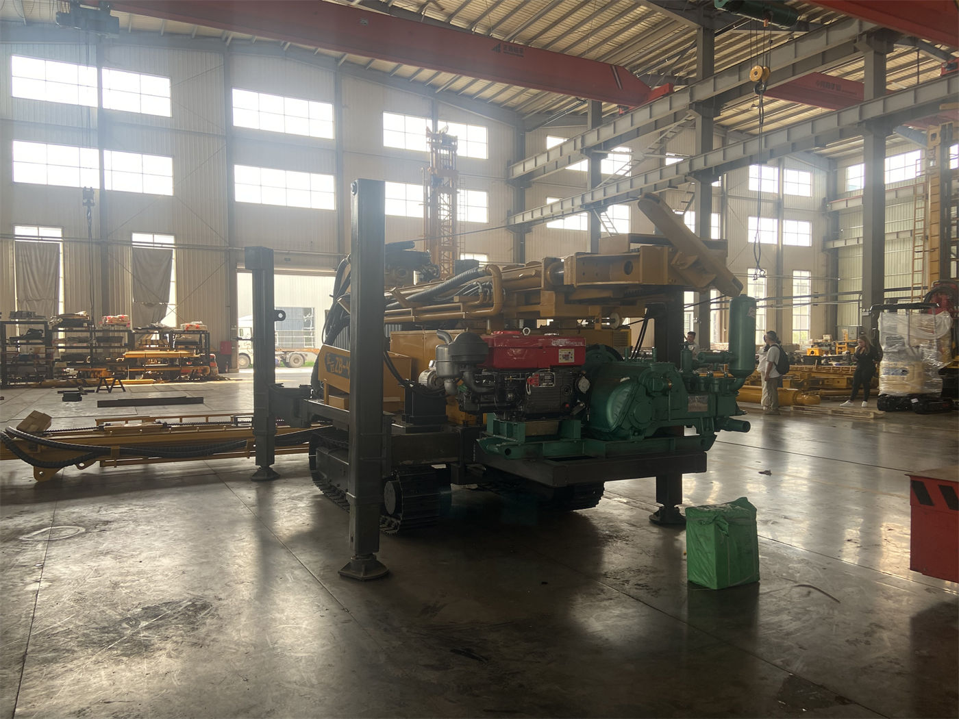
During continuous construction, the impact of this item will be reflected in equipment scheduling: if the formations at adjacent well locations differ greatly, the air compressor working state also needs to be adjusted accordingly, rather than being set once and left unchanged.
Condition 5: Crawler relocation and leveling only cover part of the site conditions
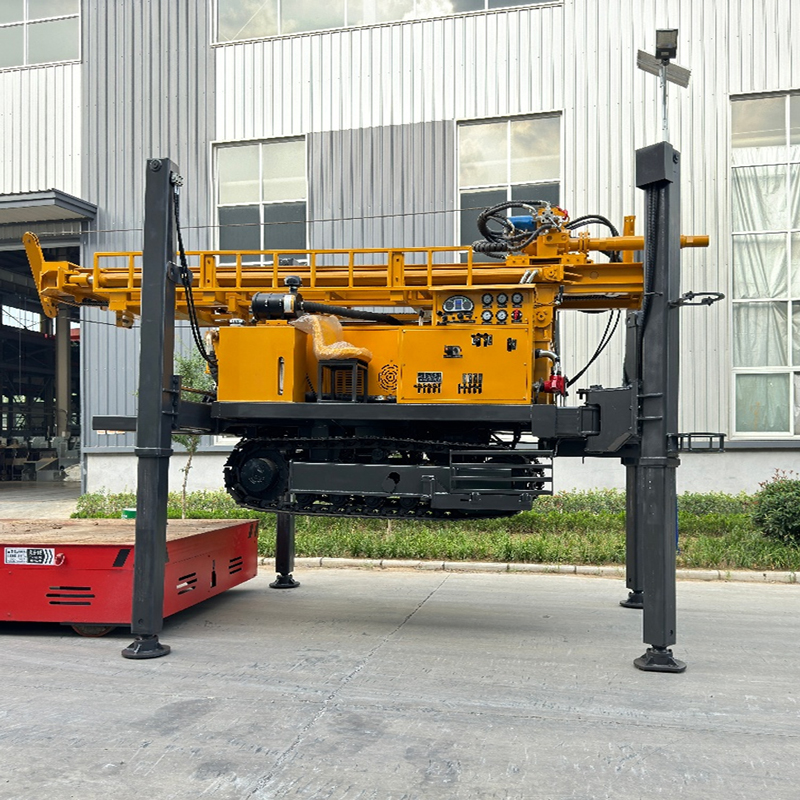
The WR350SE has a crawler chassis, with a travel speed of about 2.5 km/h and a maximum climbing angle reference of 21°. The crawler structure is suitable for rural roads, construction sites, gravel ground, and generally uneven sites. The data also reminds that before equipment relocation, the working mechanism should be retracted, and slope and ground bearing capacity should be evaluated. On wet and slippery roads and in soft soil areas, travel risks should be reduced.
The hydraulic outrigger stroke is 1.5 m, which can be used for equipment support and leveling. The data requires ensuring stable support on all sides before opening the hole. Soft ground needs to use pads to avoid settlement during construction, which affects hole inclination, tower stability, and operational safety. The total weight is about 7.5 T, and the overall dimensions are about 5.78 × 1.7 × 2.25 m. Compared with large deep well equipment, transportation and loading/unloading are easier to arrange.
It should be noted that the data only gives the equipment-side dimensions and travel parameters, and does not cover road width between well locations, turning radius, bridge and culvert load-bearing capacity, or field soil bearing capacity. These belong to site conditions and need to be verified separately according to the actual route.
Condition 6: Optional configurations should follow the working conditions
The WR350SE can be optionally equipped with a mud pump, centrifugal pump, generator, and foam pump. The corresponding relationships given in the data are: projects with more loose layers pay more attention to the mud system, hard rock projects pay more attention to the air compressor and DTH hammer, and projects lacking a stable power supply may need a generator; the foam pump can be used for some pneumatic drilling and air leakage formation treatment. Different projects do not need all configurations.
The auxiliary winch is standard at 1.1 T, with 2.5 T optional. The data explains that the standard winch is sufficient for conventional drilling tool handling; if the project has many casing, DTH hammer, or on-site lifting needs, a larger winch capacity can be selected according to actual conditions.
Several items that still need verification for continuous construction but are not covered by the data
- Actual road conditions between well locations, entry and exit times, and single-well relocation time;
- The range of formation differences between adjacent well locations, and whether processes or drilling tools need to be changed frequently;
- Water supply conditions, especially water consumption and storage methods under the mud rotary process;
- How to arrange the construction sequence of multiple wells and equipment maintenance windows;
- Actual drilling efficiency, drilling depth, and well completion results. The reference drilling efficiency given in the data is 10–35 m/h, and it is clearly stated that actual results are related to lithology, drilling tools, air compressor, and operating experience, and the final result should be based on on-site working conditions.
Looking at the above six items together, continuous irrigation well construction does not only raise the question of "whether it can drill to 350 meters," but whether drilling depth and hole diameter cover the well type, whether the rod connection method matches the site, whether both sets of processes are available, whether the air supply configuration is adjusted according to the formation, whether the chassis and outriggers adapt to the distribution of well locations, and whether optional configurations are aligned with actual working conditions. Only after verifying these conditions item by item can it be judged whether a 350-meter-class crawler water well drilling rig is suitable for undertaking a specific project.