












In the WR300SEL parameter table, three values are not difficult to understand individually, but when placed together they are easily interpreted separately: 6.6 m single feed, 1.5–6 m drill pipe compatibility, and 18 T lifting force. The first two refer to length, and the third refers to load, appearing on the surface to belong to different categories. However, when actually using the rig on a hole, these three are links in the same chain—before drilling, one first decides what length of drill pipe to use; the drill pipe length in turn constrains whether the single feed can be fully utilized; the longer the drill string, the greater its self-weight, and the lifting force must provide margin for the tripping process. This article reads the parameter table in the order of this chain, using only published data, and separately explains the parts for which the materials do not provide quantitative conclusions.
First determine what "single feed" refers to in the parameter table
"6.6 m single feed" describes the length that the power head can push the drilling tools forward in one stroke. The accompanying materials also specify that 1.5 m, 2 m, 3 m, and 6 m drill pipes can be used. Only when these two fields are read together does the coordination relationship hold: the single feed stroke must cover the length of one drill pipe so that after feeding to the end, the next pipe can be connected without stopping midway.
According to this relationship, a 6 m drill pipe fits within the 6.6 m stroke with margin; 1.5 m, 2 m, and 3 m drill pipes, after being fed within one stroke, still leave remaining stroke, which must be handled by adding a pipe or a second feed. The materials do not specify the exact connection operation rhythm for different drill pipe lengths, and this cannot be directly inferred from the parameter table.
What process does drill pipe length change?
The shorter the drill pipe, the more connections and disconnections are required for the same hole depth. Taking a 300 m hole depth as an example, if 6 m drill pipes are used throughout, one connection roughly corresponds to 6 m of footage; if 3 m drill pipes are used, the same depth requires twice as many connections and disconnections. This conversion relationship comes from the drill pipe length itself and is arithmetic, not dependent on formation conditions.
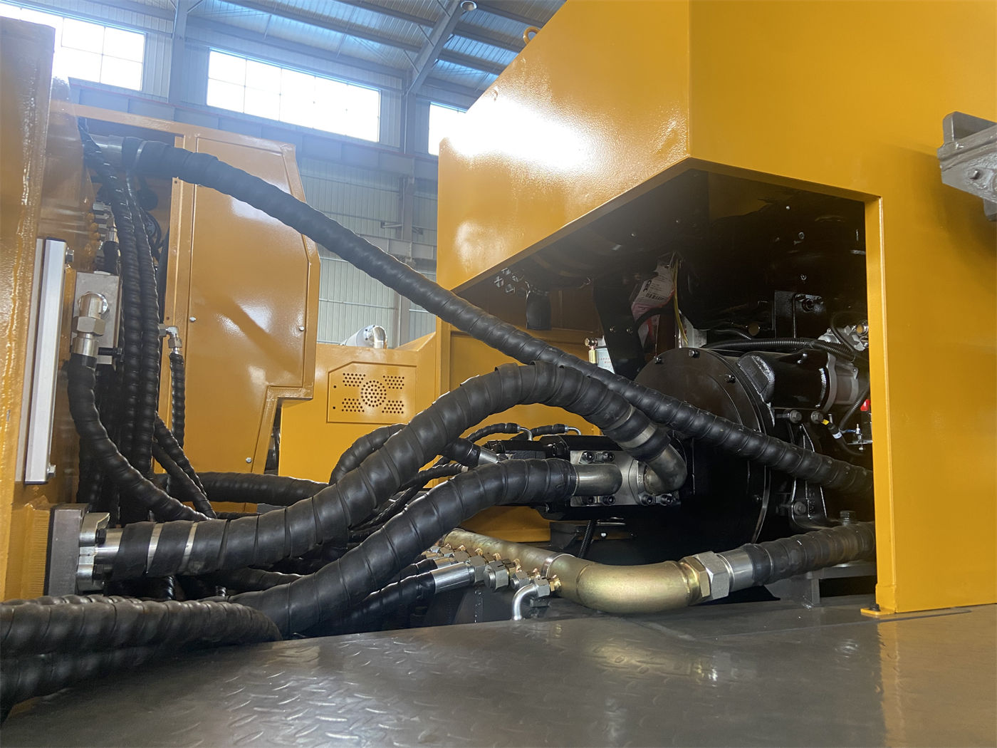
Connecting and disconnecting drill pipes is a non-drilling action that consumes construction time, and as hole depth increases, the stand length and operating steps required for each connection also change. The parameter table does not provide the time required for a single drill pipe connection, so "how much auxiliary time can be saved" cannot be directly quantified from these materials. What can be determined is the direction: under the same hole depth and same process conditions, using 6 m drill pipes results in fewer connections and disconnections than using 3 m drill pipes.
Drill pipe diameter is also written within the compatibility range
The materials list optional drill pipe diameters of 76 mm, 89 mm, and 102 mm, alongside the 1.5–6 m length range. Length and diameter are two separate sets of choices and do not form a one-to-one correspondence. Thinner and thicker drill pipes have different self-weights at the same length, which enters the lifting force discussion in the next section, but the materials do not provide the weight per unit length for each diameter, so a quantitative comparison cannot be made here.
What does the 18 T lifting force support?
The parameter table lists the lifting force as 18 T. It connects upward to the self-weight of the drill string and downward to tripping and some casing operations. As hole depth increases, the total weight of the drill pipe suspended below the lifting system increases accordingly, and borehole wall friction also accumulates as the hole section lengthens. This lifting force column must cover the sum of these loads, not the weight of a single drill pipe.
The combination of long stroke and long drill pipe places clearer requirements at this point: a longer drill pipe is connected at one time, and the drill string suspended below during a single trip may also be longer. The materials do not provide specific load values for different hole depths and drill pipe diameter combinations, nor do they provide the margin ratio for 18 T corresponding to a certain hole depth and certain drilling tool combination. Therefore, the question "is 18 T sufficient for a 300 m hole depth with 102 mm drill pipe" cannot be answered solely from this parameter table; it requires separate calculation based on the actual weight of the drilling tools and downhole conditions.
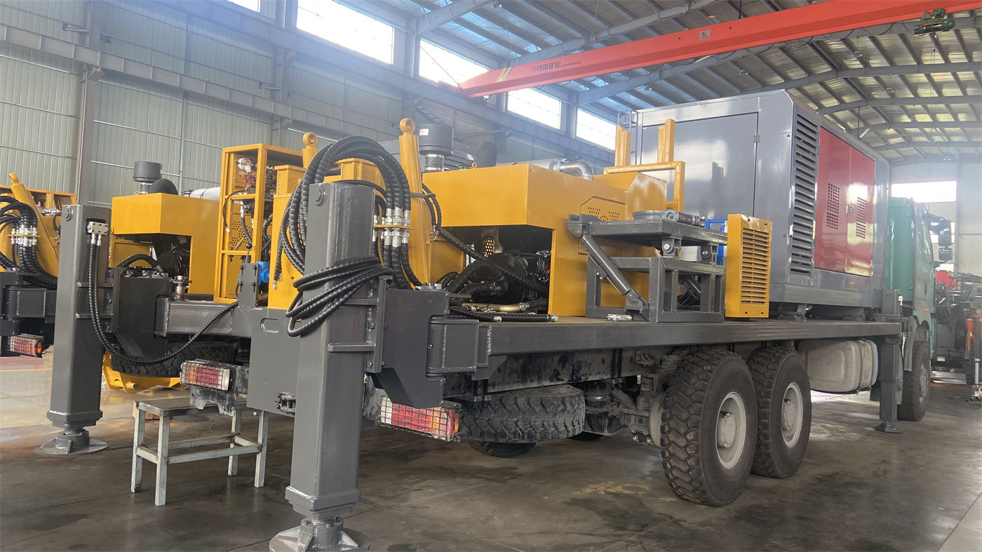
Beyond lifting force, the same process also has supporting items
There are two other values in the materials related to tripping: 22 m/min fast lifting and 40 m/min fast feed, as well as a 2 T auxiliary winch. Fast lifting and fast feed correspond to the speed of non-drilling actions, and the auxiliary winch can be used to handle drill pipes, down-the-hole hammers, and casing tools. These items, together with the 18 T lifting force, form the supporting set for the tripping process, but each handles a different link and the 2 T of the auxiliary winch cannot be included in the main lifting force calculation.
Put the three parameters back into the same hole
Assume a 300 m class water well project using 6 m drill pipes and operating with 6.6 m single feed. Then the chain works as follows: the single feed stroke covers one drill pipe length, and the number of connections unfolds in 6 m increments; the self-weight of the drill string brought by the increased drill pipe length must be borne by the 18 T lifting force; the non-drilling time during tripping is shared by fast lifting, fast feed, and the auxiliary winch.
If 3 m drill pipes are used instead, the segment of the chain "single feed covers one drill pipe" still holds, but the number of connections doubles, the proportion of non-drilling action time rises, and the load composition faced by the 18 T lifting force also changes accordingly—the drill string for a single trip is shorter, but the total number of connections and disconnections is greater. The two choices correspond to different construction organization methods, not simply a difference in efficiency.
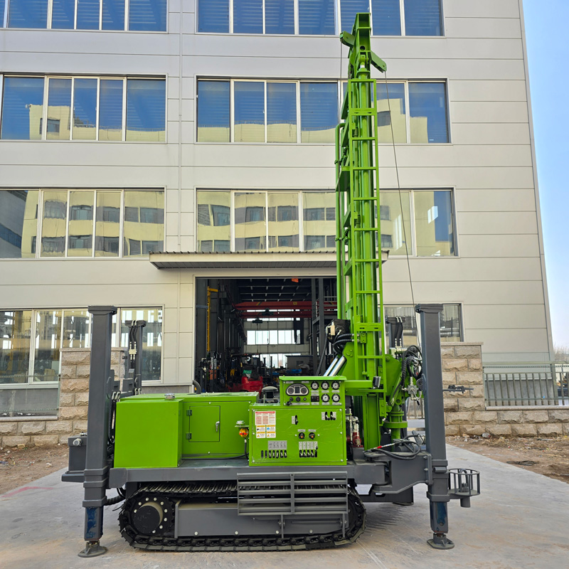
Other values in the parameter table related to the coordination relationship
There are several other items in the same materials that are affected by this chain, listed together for easy reference:
| Parameter | Data | Relationship to drill pipe coordination |
|---|---|---|
| Single feed length | 6.6 m | Determines the drill pipe length that can be covered in a single stroke |
| Drill pipe length | 1.5 / 2 / 3 / 6 m | Affects the number of connections and the distribution of drill string self-weight |
| Drill pipe diameter | 76 / 89 / 102 mm | Together with length determines drill string weight |
| Lifting force | 18 T | Supports drill string self-weight, borehole wall friction, and casing |
| Fast lifting / fast feed | 22 m/min / 40 m/min | Affects non-drilling action time |
| Auxiliary winch | 2 T | Used for handling drill pipes, down-the-hole hammers, and tools |
This table only serves as a reminder of the combination relationships and does not imply that conversion formulas exist between the parameters. The parameter table provides independent values, and the coordination relationships must be inferred according to the process.
Questions this parameter table does not answer
- For completing the same well with 6 m drill pipes versus 3 m drill pipes, the specific difference in the number of connections can be calculated by hole depth, but the time per connection and the total time saved are not provided in the materials, so a quantitative conclusion cannot be drawn.
- The margin of the 18 T lifting force under different hole depths and drill pipe diameter combinations is not provided in the materials.
- The weight per unit length of the 76 mm, 89 mm, and 102 mm drill pipe diameters is not listed in the materials, so the drill string self-weight cannot be estimated from them.
- The actual requirements of the long stroke configuration on site clearance and drill pipe handling are only described suggestively in the materials, without specific site dimension thresholds.
These items need to be separately confirmed with the supplier during selection or mobilization. What the parameter table can determine is the corresponding categories between length and load; it cannot replace load calculations for specific drilling tool combinations and hole depth conditions.