












In the WR220SE materials there is a description that is often skipped: supports dual water-air drilling. In selection discussions, this sentence is often compressed into "one machine, two drilling methods," but the parameter table itself does not provide a switch item for this statement. To answer "what exactly is switched," one can only lay out the components and parameters that appear in the materials item by item, and see which change with the process and which do not. The following uses only the product materials published on this site; parts not covered by the materials are marked separately.
Where the term "dual-purpose" appears in the materials
In the WR220SE parameter table, there are three fields directly related to the drilling method: the drilling method column states "dual water-air"; the air compressor matching parameters column gives a working air pressure of 1.7–2.5 MPa and air consumption of 17–31 m³/min; and the main text mentions that "for soil layers, clay, and loose overburden, priority can be given to hole stabilization and cuttings discharge; after entering weathered rock or relatively intact rock formations, pneumatic drilling can be adopted with a DTH hammer and air compressor."
The three places point to three different levels: overall machine positioning, external matching, and downhole tools. This shows that "dual water-air" is not the state of a valve inside the equipment, but the ability of the same main machine to combine with different external tools and media under different formation conditions.
Switching point 1: The medium entering the hole
The most intuitive layer is that the medium sent into the hole during drilling differs. The water drilling direction relies on liquid medium to cooperate with hole stabilization and cuttings discharge; the pneumatic direction relies on compressed air to drive the downhole DTH hammer and handle cuttings discharge. The medium changes from water to air, and this change is not completed by the main machine alone; in between there are also the air compressor, air hose, and oil mist lubricator, among other matching components.
The working air pressure of 1.7–2.5 MPa and air consumption of 17–31 m³/min given in the materials describe the requirements of the pneumatic direction on the air compressor, not the output of the main machine itself. When the hole diameter increases, the rock formation becomes harder, or the altitude rises, the materials clearly indicate that the requirement for air compressor displacement will be higher. In other words, whether the pneumatic direction can be established depends first on constraints outside the main machine.
Switching point 2: Downhole drilling tools
The materials state in the section on weathered rock and relatively intact rock formations that after entering relatively intact rock formations, a suitable DTH hammer, drill bit, and air compressor should be used. The DTH hammer appears only in the pneumatic direction; the water drilling direction corresponds to another set of drilling tools.
This is the most easily underestimated point in dual water-air drilling: switching is not only medium replacement, but the drilling tools themselves also need to be changed. The same drill pipe can be reused under both processes, but the working components at the downhole end differ. The materials do not give the specific drilling tool model for the water drilling direction; this part needs to be confirmed with the manufacturer.
Switching point 3: Hole wall treatment and cuttings discharge path
The materials describe sand layers, gravel layers, and loose overburden as "prone to hole collapse, drill burial, and hole diameter enlargement," and the treatment direction is "priority should be given to hole wall protection and casing follow-up; when necessary, water drilling or other hole stabilization methods should be used; it is not recommended to rely solely on pneumatic drilling to quickly pass through."
Conversely, in fractured zones and fissured formations, the pneumatic direction also faces air leakage, block falling, drill sticking, and abnormal cuttings discharge. The materials recommend reducing the advancement speed, maintaining continuous hole cleaning, and observing changes in air pressure and return water. It can be seen that the failure modes of cuttings discharge path and hole wall stability differ under the two processes. What actually needs to be changed during switching is a whole set of in-hole response methods, not just a medium inlet.
Which parts do not switch with the process
After excluding the switching points above, most values in the parameter table remain unchanged under both processes:
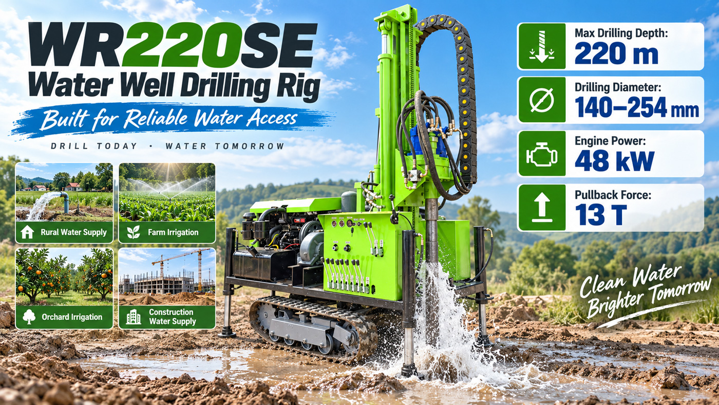
- Maximum drilling depth 220 m
- Drilling diameter 140–254 mm
- Drill pipe diameter Φ76 / Φ89 mm, drill pipe length 1.5 / 2.0 / 3.0 m
- Mast height 2.6 m, single advancement length 3.3 m
- Lifting force 13 T, fast lifting speed 30 m/min, fast advancement speed 60 m/min
- Rotary torque 3400–4700 N·m, rotary speed 45–70 rpm
- Engine Yuchai 48 kW
- Overall machine approximately 4.7 T, dimensions approximately 3950 × 1750 × 2250 mm, travel speed approximately 2.5 km/h, maximum gradeability reference 30°
These values describe the main machine and travel system and do not change with the drilling medium. In the rotary section, the materials mention that rotary parameters should match the drill pipe, drill bit, DTH hammer, and formation; stable rotation speed can be maintained in intact rock formations, and rotation speed and advancement should be appropriately reduced in fractured zones or when resistance increases—this is an operational adjustment, not a configuration-level switch.
Looking at switching points and non-switching items together
| Item | Water drilling direction | Pneumatic direction |
|---|---|---|
| In-hole medium | Liquid medium, used for hole stabilization and cuttings discharge | Compressed air, working air pressure 1.7–2.5 MPa, air consumption 17–31 m³/min |
| Downhole drilling tools | Corresponding water drilling tool combination | DTH hammer with corresponding drill bit |
| External matching | Specific matching not listed in the materials | Air compressor, air hose, oil mist lubricator |
| Main machine and travel | Mast, lifting force, rotation, engine, and crawler parameters remain unchanged |
Reading in formation order, when does switching occur
The materials do not give criteria such as "when you see what, use water drilling; when you see what, use air drilling." What can be determined is its treatment direction for different formations: soil layers, clay, and loose overburden focus on hole stabilization and cuttings discharge; weathered rock drilling is faster but the hole wall may be unstable, so advancement speed should be controlled and casing or hole cleaning measures taken promptly; after entering relatively intact rock formations, use a DTH hammer and air compressor; for sand layers, gravel layers, and water-rich loose layers, priority should be given to hole wall protection and casing follow-up; in fractured zones and fissured formations, reduce advancement speed, maintain continuous hole cleaning, and observe changes in air pressure and return water.
In other words, the timing of switching is determined by the actual in-hole conditions, and the observable quantities provided by the materials are block falling, diameter shrinkage, return water, air pressure, and cuttings discharge. These are on-site judgment bases, not thresholds on the parameter table.
Matters not answered by the materials and requiring separate confirmation
- The specific external matching list for the water drilling direction; the materials do not list corresponding equipment and consumables.
- The drilling tool models and specifications used in the water drilling direction; the materials do not provide them.
- How the two processes are connected within the same hole (for example, whether to change rods, whether to stop drilling to treat the hole wall); the materials do not explain this.
- The specific displacement and pressure of the air compressor required for the pneumatic direction should be selected according to DTH hammer specifications, hole diameter, hole depth, and altitude; the materials only give a reference range and do not provide a selection correspondence table.
- The medium supply method and consumption for the water drilling direction; the materials do not cover this.
Therefore, understanding dual water-air drilling as "flipping a switch at some location" is not accurate. According to the published materials, what changes with the process are the in-hole medium, downhole drilling tools, and corresponding external matching, as well as the corresponding hole wall treatment and cuttings discharge methods; the main machine, mast, lifting, rotation, and travel parameters maintain the same set of values under both processes. Actual hole depth, efficiency, and well completion effects should, as the materials clearly state, be based on on-site working conditions.