












The construction pace during the farmland irrigation season differs from a single deep-hole project: there are many well sites, well depths are usually within 200 meters, and the formations may not be the same for every well, but each well requires the entire set of operations to be carried out from start to finish. The WR200SE materials state "maximum drilling depth 200 m, drilling diameter 140–254 mm, reference drilling efficiency 10–35 m/h"; these values correspond to the drilling phase. What actually consumes the schedule are the other operations before and after drilling, as well as their repetition across multiple wells. The following is organized in the order of one well from entry to exit, using only the product materials published on this site; parts not covered by the materials are marked separately.
1. Entry and Positioning
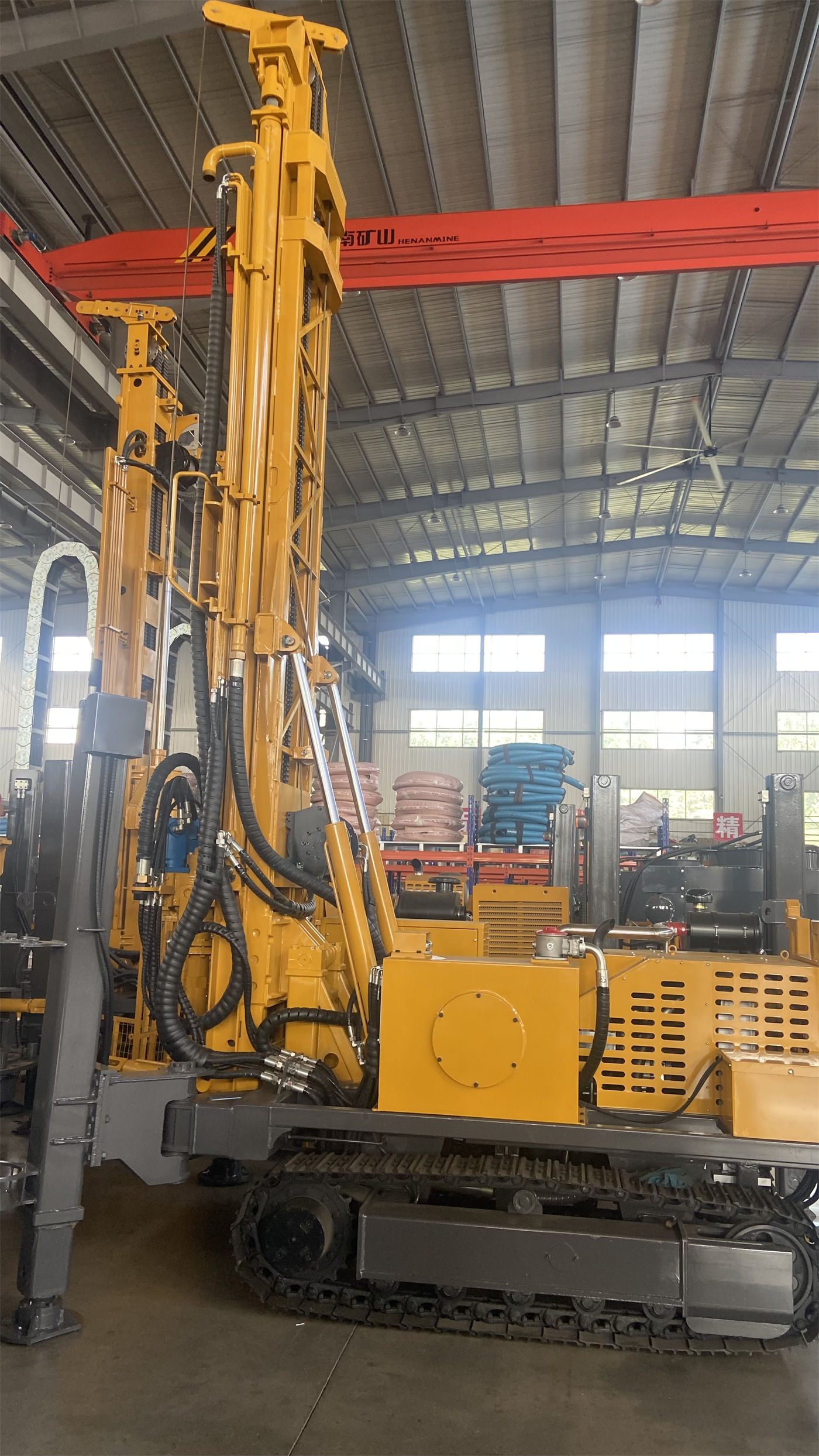
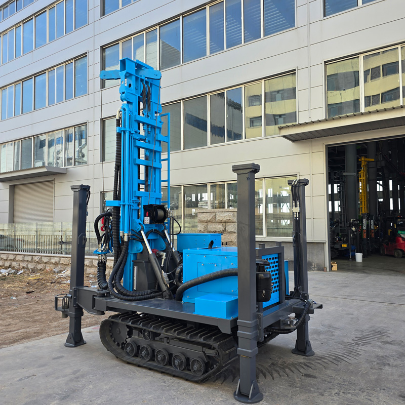
The WR200SE is a crawler-type structure with an overall weight of approximately 4.7 T, dimensions of approximately 3950 × 1750 × 2250 mm, and a travel speed of approximately 2.5 km/h. Taken together, these figures correspond to a specific entry process: unloading from the transport vehicle, moving along village roads or field paths to the well site, and then completing alignment at the well site.
What is consumed in this step are the capabilities of the chassis and the outriggers. The 1.4 m outrigger stroke is used for supporting and leveling on uneven ground. The materials do not specify the specific ground bearing requirements, only mentioning that pads can be added when necessary. Farmland plots vary greatly in softness before and after the irrigation season. Whether the outrigger placement is stable and whether the mast tilts after being raised must be judged on site and cannot be based solely on the outrigger stroke value.
2. Hole Opening and Upper Overburden
The materials describe the upper formations as follows: directly using a down-the-hole hammer in soil, clay, sand, or gravel layers is not necessarily the best solution. Loose overburden is prone to hole collapse, drill burial, and hole diameter enlargement. The upper hole section should first be treated with casing, mud, or other hole stabilization methods.
The corresponding operations in this section are hole opening and wall protection. The available equipment conditions are a drilling diameter of 140–254 mm and drill rod specifications of 76 / 89 mm. As for how large the hole diameter should be, the materials provide a range rather than a conclusion, and note that "for agricultural wells requiring long-term pumping, the well diameter, filter pipe, and pump type should be determined before construction based on the expected water yield, rather than simply pursuing a larger hole diameter." This section uses a different process from rock drilling, and the operation arrangement needs to be determined in advance.
3. Drilling and Rod Connection
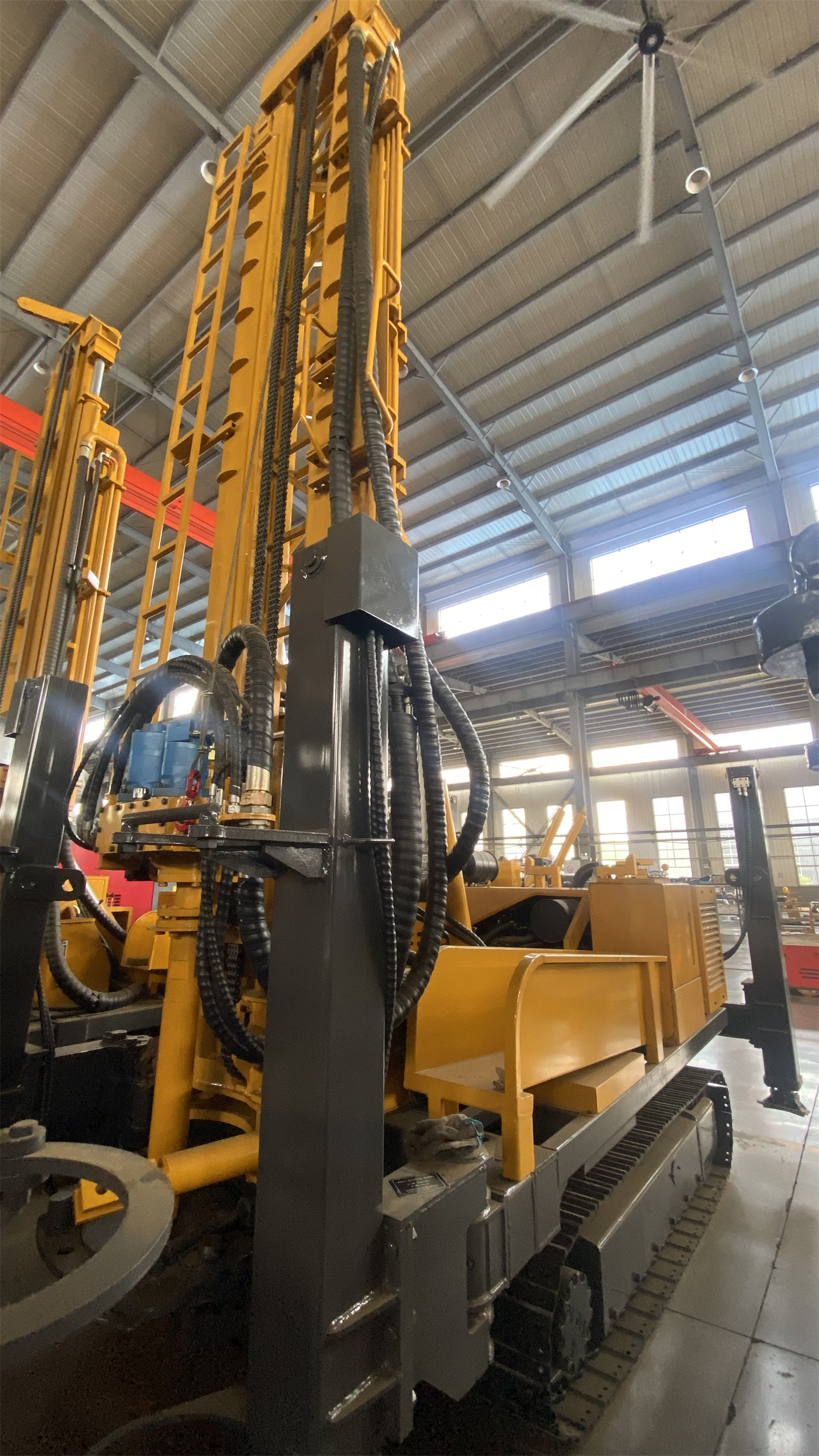
After entering rock formations, rotation and feed are continuously performed operations. The reference values are: rotary torque 3400–4700 N·m, rotary speed 45–70 r/min, fast lifting speed 30 m/min, fast feed speed 60 m/min, lifting force 13 T.
The rod connection operation is constrained by two length parameters: the telescopic mast has a single feed length of 3.3 m and can be equipped with 1.5 m, 2.0 m, and 3.0 m drill rods. The combination of a 3.0 m drill rod with a 3.3 m single feed determines the stroke achievable per rod connection; when using 1.5 m drill rods, the number of rod connections increases accordingly. The materials do not provide a quantitative relationship between different drill rod combinations and auxiliary time, only stating that fast lifting and fast feed are used for power head movement and drill rod handling in non-drilling states, which can reduce auxiliary time such as loading and unloading drill rods.
The reference drilling efficiency of 10–35 m/h is stated in the materials, but the same materials also state: actual rock penetration rate depends on rock properties, down-the-hole hammer, drill bit, and air compressor capacity. This value is a reference range and cannot be directly converted into the completion time of a single well.
The Role of Air Supply in This Section
Reference working pressure 1.7–2.5 MPa, air consumption 17–31 m³/min. The materials note that when the hole diameter increases, the rock formation hardens, or the altitude rises, a more sufficient displacement is usually required. Insufficient air compressor matching will directly affect impact frequency, cuttings removal, and drilling efficiency. The air compressor is not part of the drilling rig itself; when selecting it, it must be checked separately according to the target hole diameter, hole depth, and rock formation.
4. Treatment After Entering the Aquifer
The materials explain this section as follows: after drilling into the aquifer, water inflow will change the cuttings removal state in the hole and the working conditions of the down-the-hole hammer. The air compressor supply and hole cleaning method should be adjusted according to the actual water yield, and the aquifer depth should be recorded promptly. Before well completion, the well casing, filter pipe, and water stop structure also need to be reasonably arranged according to the water layer conditions.
For irrigation wells, this section determines how the subsequent well casing and filter pipe are installed. The equipment side can provide drilling depth and hole diameter margin (200 m, 140–254 mm), while the well casing structure, filter pipe position, and water stop method belong to well completion design. The materials only give direction, not specific methods.
5. Well Completion, Casing Installation, and Well Washing
In the well completion stage, the equipment conditions mentioned in the materials are mainly a lifting force of 13 T, which can be used for normal tripping, drill rod handling, and some casing operations, as well as a winch lifting force of 1.5 T (auxiliary). For the casing installation step, the materials do not provide the specific diameter and single length of compatible casing, nor do they provide well completion process parameters suitable for irrigation wells. This part needs to be confirmed separately according to the project.
Well washing has no corresponding parameters or step descriptions in the provided materials, so this article does not elaborate on its process content.
6. Moving and the Next Well
The irrigation season is characterized by scattered well sites and relatively fixed workload per well. The moving step relies on the crawler chassis capability: travel speed approximately 2.5 km/h, maximum gradeability reference 30°. The materials also state that when moving on slopes, the center of gravity should be lowered, the mast retracted, and ground adhesion conditions confirmed. The actual safe gradeability should be judged according to site conditions.
There is also a note on site selection in the materials worth placing in this section: during construction, well sites should be reasonably determined based on local groundwater data, avoiding reliance solely on increasing drilling depth to compensate for site selection errors. The denser the well sites and the more variable the formations, the greater the impact of this point on the arrangement of the moving sequence.
Putting the Operations of an Irrigation Season into One Table
| Operation | Corresponding Equipment Conditions | Not Covered by Materials |
|---|---|---|
| Entry and positioning | 4.7 T, 3950 × 1750 × 2250 mm, 2.5 km/h, 1.4 m outrigger stroke | Specific ground bearing requirements, pad conditions |
| Hole opening and upper overburden | Hole diameter 140–254 mm, drill rod 76 / 89 mm | Specific selection and amount of wall protection method |
| Rock drilling and rod connection | Torque 3400–4700 N·m, speed 45–70 r/min, 3.3 m single feed, 1.5 / 2.0 / 3.0 m drill rods | Auxiliary time under different drill rod combinations |
| Air supply | Working pressure 1.7–2.5 MPa, air consumption 17–31 m³/min | Displacement calculation for specific hole diameter and depth |
| Aquifer and well completion | 13 T lifting force, 1.5 T winch | Compatible casing specifications, well casing and filter pipe arrangement |
| Well washing | Not covered by materials | Entire process |
| Moving | 2.5 km/h, 30° reference gradeability | Limits under specific site conditions such as soft soil and slopes |
The purpose of this table is not to match each operation to a parameter, but to see which operations have parameters to rely on and which operations have no corresponding items in the materials. For the parts with parameters, the configuration can be checked against the values to see if it is sufficient; for the parts without parameters, separate confirmation is needed during the selection and entry arrangement stages.
Matters Not Answered by the Materials and Requiring Separate Confirmation
- The specific process of well washing and the degree of equipment involvement are not mentioned in the materials.
- The diameter and single length of compatible casing are not provided in the materials.
- The matching method of filter pipe and pump type under common well diameters for irrigation wells is only noted in the materials as needing to be determined before construction.
- The actual completion time of a single well under a specific formation combination: the materials provide a reference drilling efficiency of 10–35 m/h, which cannot be directly converted.
- The number of rod connections and auxiliary time corresponding to different drill rod length combinations: the materials do not provide a quantitative relationship.
- Daily pre-start inspection items are listed in the materials as hydraulic lines, rotary head, winch, crawler, mast, and drill rod connections, etc. Specific inspection standards need separate confirmation.
When several wells are drilled consecutively during the irrigation season, the operations themselves are not complicated. The difficulty lies in whether the conditions for each operation are in place before starting work. For parts covered by parameters, the parameter table shall prevail; for parts not covered by parameters, they need to be confirmed clearly before entry.