












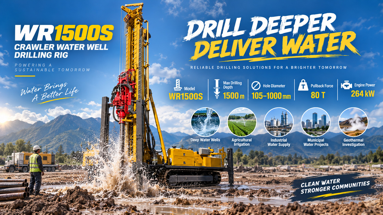
In the WR1500S documentation, the complete machine weighs about 28 T, has overall dimensions of about 11.5 × 2.6 × 3.5 m, supports 9.6 m drill pipes, has a maximum drilling depth of 1500 m, and a lifting force of 80 T. These values are not difficult to understand individually, but taken together they point to the same thing: before this equipment is mobilized, there are several more groups of conditions to confirm than for small and medium-sized water well drilling rigs, and these groups are not parallel. If one group is not confirmed, it directly changes whether the subsequent processes can be executed as planned.
The following is organized in the order of first calculating the downhole load, then verifying hole diameter and drilling method, then moving to site and transport, and finally connecting the supporting air supply. Parts not given in the documentation are marked separately.
Group 1: Where to start calculating the drill string load at 1500 m hole depth
In deep hole construction, drill string weight, hole wall friction, casing weight, and local sticking occur in combination. The closer to the bottom of the hole, the more concentrated the load is during tripping. The WR1500S provides a lifting force of 80 T, an axial pressure of 16 T, a fast lifting speed of 28 m/min, a fast advancing speed of 44 m/min, and recommended drill pipe diameters of 114 / 127 mm.
Before mobilization, the specifications and segment lengths of drill pipes and casing need to be confirmed. A 9.6 m drill pipe can reduce the number of connections and disconnections, but it also requires sufficient operating space on site and more standardized drill pipe handling organization; drill pipes usually need to be transported separately, which must be scheduled during loading. The documentation does not provide a drill string weight calculation table for different hole depths and hole diameters, so this part must be calculated independently based on the actual weight of the selected drill pipes.
Group 2: Hole diameter range and drilling method determine which process is used for this hole
The WR1500S has a drilling diameter of 105–1000 mm, covering conventional deep water wells, large-diameter groundwater wells, mine dewatering, and some large engineering holes. The larger the hole diameter, the higher the requirements for the air compressor, drilling tools, casing, rotary torque, and lifting capacity. Therefore, actual projects should select a reasonable hole diameter according to the well completion target, rather than organizing according to the upper limit.
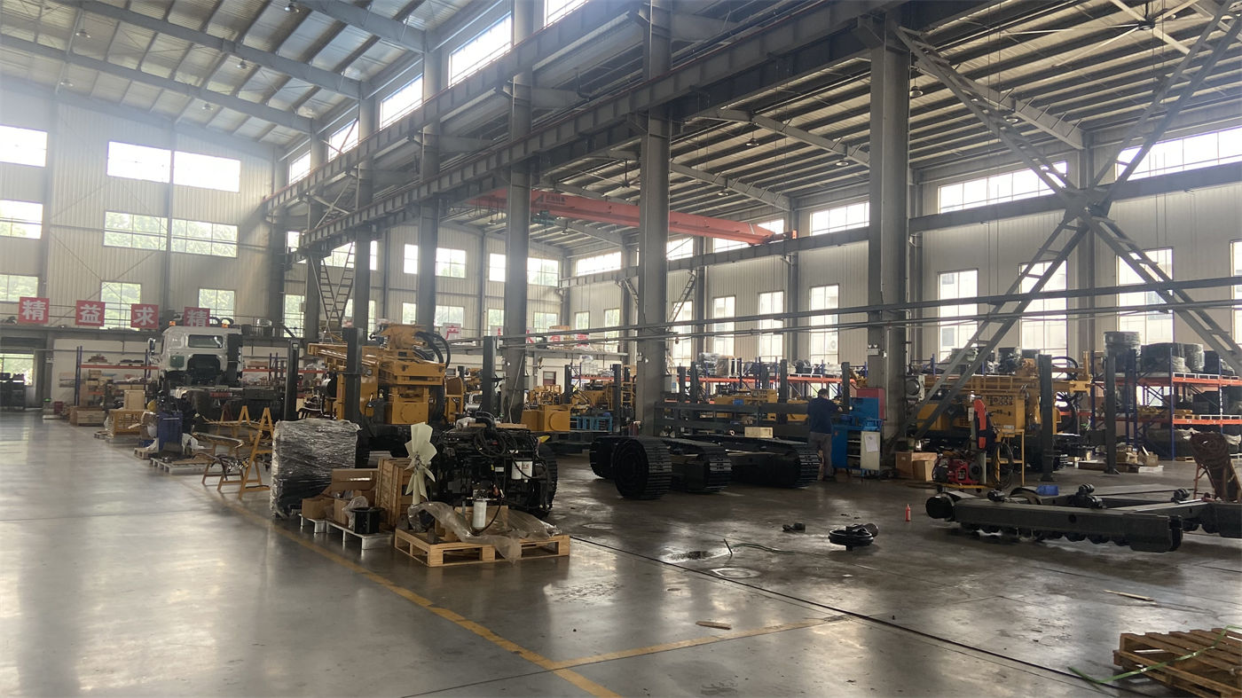
The documentation gives three types of drilling methods, corresponding to different hole sections:
| Drilling method | Corresponding conditions in the documentation |
|---|---|
| Top drive hydraulic rotary drilling | Conventional deep water wells and large-diameter drilling |
| DTH down-the-hole hammer drilling | Weathered rock, fractured rock, and intact hard rock |
| Mud rotary drilling | Loose formations such as soil, clay, sand, and gravel layers |
The upper and lower sections of the same 1500 m hole may not use the same method. Before mobilization, the hole body sections and corresponding processes must be laid out first. The recommended working air pressure of 1.65–8 MPa and air consumption of 16–120 m³/min in the documentation apply only to the DTH down-the-hole hammer drilling section.
The rotary and torque column must also follow the hole section
Maximum rotary torque is 31000 / 15500 N·m, and maximum rotary speed is 70 / 140 r/min. Low speed and high torque are more suitable for large-diameter, hard rock, and high-friction conditions, while higher speeds are suitable for stable hole sections with relatively low resistance. How to use these two values depends on the actual state of the hole section. The documentation does not provide a comparison table for selecting torque according to hole diameter and rock formation.
Group 3: Mobilizing a 28 T complete machine requires transport and site planning around this weight
The complete machine weighs about 28 T, has a travel speed of 3.5 km/h, a maximum climbing angle of 21°, a hydraulic leg stroke of 1.7 m, and a telescopic mast structure. These items correspond to the two processes of mobilization and positioning.
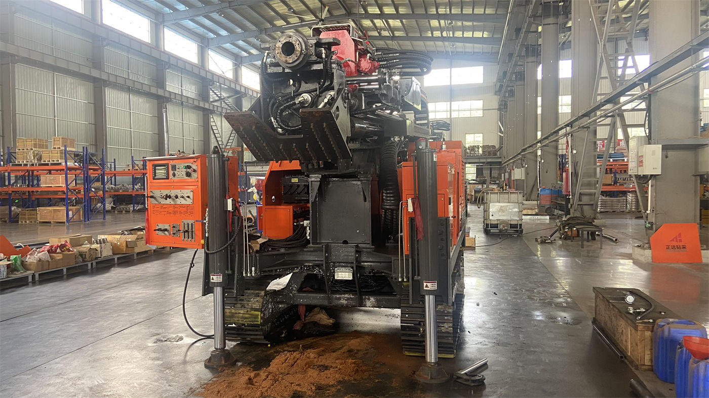
- For cross-regional transport, the flatbed load capacity, road height restrictions, bridge load capacity, and turning space must be confirmed in advance; the telescopic mast can improve the overall transport profile, but it will not change the 28 T weight class.
- 9.6 m drill pipes usually need to be transported separately, and the loading method must be determined before shipment.
- After arriving on site, in addition to the drilling rig itself, space must be reserved for the air compressor, mud system, drilling tools, and material area.
- The hydraulic leg stroke is 1.7 m, and the leveling and support plan during positioning must be planned according to this parameter.
The documentation does not provide ground pressure values, and the foundation bearing capacity must be confirmed separately based on site conditions.
Group 4: The air compressor and supporting air supply cannot wait until startup to be determined
During DTH down-the-hole hammer drilling, the recommended working air pressure is 1.65–8 MPa, and air consumption is 16–120 m³/min. For 1500 m class deep holes and large-diameter hard rock projects, the air compressor displacement requirements are very high. Pressure and displacement must simultaneously meet the needs of the down-the-hole hammer and bottom-hole cuttings removal; otherwise, insufficient impact, difficult cuttings removal, and bottom-hole cuttings accumulation are likely.
If the project is to switch to mud rotary drilling, mud pumps, centrifugal pumps, generators, and foam pumps are listed among the optional accessories. The connection method between supporting equipment and the rig must be determined before mobilization.
Group 5: Auxiliary winches and lifting operations must be arranged according to rated load
The equipment is equipped with a 5 T large auxiliary winch and a 2.5 T small auxiliary winch, which can be used for handling down-the-hole hammers, drill pipes, casing tools, and general accessories. Ultra-deep hole projects have many supporting tools and large individual weights. Dual winches can reduce manual handling intensity, but lifting operations must strictly comply with rated loads and safety distances. Before mobilization, check the actual tool weights to confirm which winch is needed and what lifting gear is used.
Inspection items on the day of mobilization, as mentioned in the documentation
The documentation explicitly states that before daily startup, the engine, hydraulic system, telescopic mast, legs, tracks, dual winches, high-pressure air pipes, and 9.6 m drill pipes should be inspected. During deep hole construction, torque, air pressure, cuttings return, water return, and pull-out resistance need to be continuously recorded; when trend abnormalities are found, the machine should be stopped promptly for analysis. This part of the documentation gives inspection objects and recording items, but does not give judgment thresholds for various parameters.
The documentation also indicates that when cuttings return continues to decrease or pull-out resistance increases significantly, drilling should be stopped promptly for inspection; when encountering weathered rock, fractures, or fault fracture zones, the advancing speed should be reduced, hole cleaning strengthened, and casing, foam, or other hole stabilization measures used according to actual conditions. These are judgments during the construction process. In the pre-mobilization preparation stage, the main task is to assign these judgment bases to people and record sheets.
Items not covered by this site's documentation and requiring separate confirmation
- Calculation tables for drill string weight and lifting margin under different hole depths, hole diameters, and drill pipe specifications;
- Comparison relationships for selecting rotary torque and speed according to formation and hole diameter;
- Ground pressure, foundation bearing capacity, and specification requirements for leg pads;
- Selection recommendations for specific air compressor displacement and pressure combinations;
- Flatbed tonnage, ramp slope, and securing method for complete machine transport;
- On-site personnel configuration and division of labor requirements.
Actual drilling efficiency, achievable drilling depth, and well completion results will be affected by geological conditions, downhole tools, drilling angle, and operating methods, and are still subject to on-site conditions.