












The larger the drilling depth rating, the higher the price, transport weight, site footprint, and mobilization time will rise in tandem. Therefore, the real difficulty in the question of "which grade to deploy" is not whether a certain depth can be drilled, but rather first determining whether the target well depth truly requires this grade of equipment. For the 1000 m-class and above models published on this site, the drilling depths given in the materials are 1000 m, 1200 m, and 1500 m respectively, but the differences among the three are not limited to these three numbers. The following proceeds through an executable sequence of judgment, with each step using only the values and descriptions appearing in the materials.
Step 1: Break the target well depth into "must drill" and "may drill"
A machine's "maximum drilling depth" is its capability ceiling, while the design depth of a specific well is determined by hydrogeological data, the burial depth of the target aquifer, and the completion structure. These are not the same thing. Taking the WR1000S as an example, the materials state a maximum drilling depth of 1000 m and a borehole diameter of 105–800 mm, while also clearly noting that "the actual well depth still needs to be determined based on hydrogeological data, formation structure, and the target aquifer." Read in reverse, this means: if the target aquifer in a certain area generally lies at 700–800 m, then the reason for choosing 1000 m-class equipment is not "we'll drill to 1000 m anyway," but rather to leave margin in drilling depth, drill string handling capacity, and completion structure within that range.
Therefore, the first thing to establish is to divide the well depths in the project into two columns: the depth that most wells actually need to reach, and the deepest value that individual wells may reach. The former determines the equipment's routine working range, while the latter determines how much reserve the capability ceiling should have. The materials do not provide a quantitative standard for "how much margin is appropriate," so this column needs to be confirmed separately based on actual project conditions.
Step 2: Hole diameter and completion structure will inversely change the depth judgment
The same grade of equipment carries different loads at different hole diameters. The WR1000S has a hole diameter range of 105–800 mm, a very wide span. One qualification in the materials requires special attention: "The larger the hole diameter, the higher the requirements for the air compressor, drilling tools, casing, and overall machine load, so routine construction cannot be based solely on the maximum hole diameter." This indicates that the 800 mm upper limit is closer to a capability boundary rather than a common hole diameter for long-term stable operation.
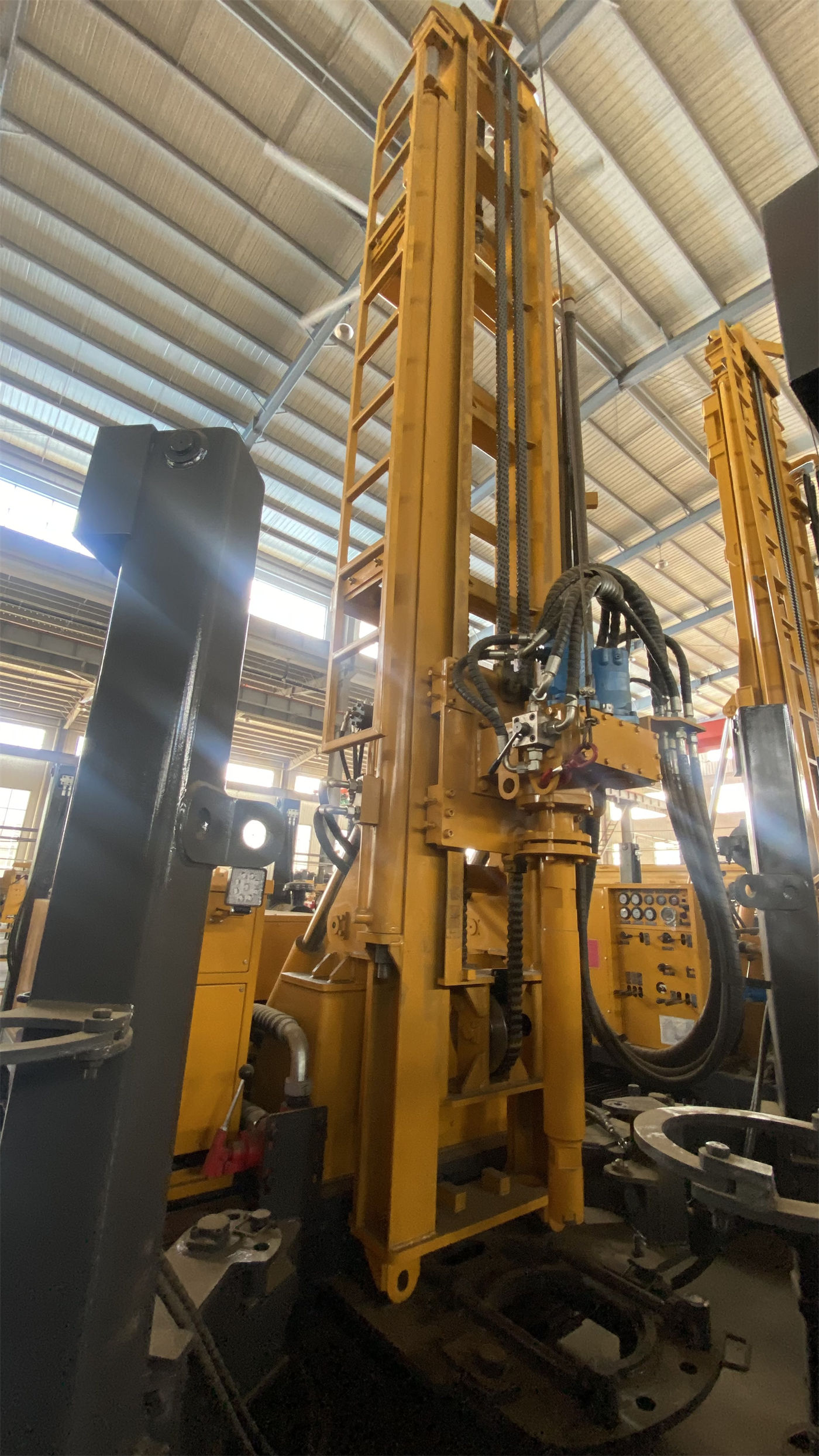
This step follows Step 1 because the completion structure determines casing specifications, screen sizes, and whether a larger well diameter is needed. If large-diameter casing must be installed later in the project or a high-flow pumping structure is adopted, then at the same well depth, the actual load on the equipment will be significantly higher than with a conventional well diameter plan. At this point, returning to Step 1 to recheck the depth margin is more prudent than directly selecting equipment based on drilling depth.
Step 3: Verify drill string load using lifting force and torque, not drilling depth
Drilling depth itself does not generate load; the load comes from the drill string in the hole. Taking the WR1000S as an example, the relevant values given in the materials are: 52 T lifting force, 8 T axial pressure, 26000 / 13000 N·m rotary torque, maximum rotation speed 70 / 140 r/min, recommended drill pipe diameter 114 mm, and support for 6 m drill pipes. Only by considering these values together can the drill string control capability at 1000 m-class hole depth be explained.
| Parameter | WR1000S | Description |
|---|---|---|
| Maximum drilling depth | 1000 m | Capability ceiling, not equal to the design depth of every well |
| Borehole diameter | 105–800 mm | Large hole diameters correspond to higher loads and should not be used as routine hole diameters |
| Lifting force | 52 T | Used for tripping, drill tool recovery, and some large-specification casing operations |
| Rotary torque | 26000 / 13000 N·m | Low speed and high torque for large hole diameters, hard rock, and high-friction hole sections |
| Drill pipe | 6 m, recommended diameter 114 mm | Reduces deep-hole connection and disconnection frequency, lowering auxiliary time and labor intensity |
| Working air pressure | 1.6–8 MPa, air consumption 16–96 m³/min | Must be comprehensively determined based on DTH hammer, hole diameter, hole depth, altitude, and rock hardness |
Regarding lifting force, the materials state: "At 1000 m-class hole depths, drill pipe self-weight, borehole wall friction, casing weight, and local sticking all place higher demands on the lifting system." This indicates that lifting force does not only serve normal tripping. It must also provide operating space under abnormal downhole conditions. However, the materials do not provide a quantitative result for "how much higher the lifting force should be than the drill string self-weight," and the actual loads under conditions such as sticking, hole shrinkage, and block falling need to be judged based on project records.
Step 4: Drill pipe length and mast type determine the process, not just transport
The significance of 6 m drill pipes for 1000 m-class hole depths is stated directly in the materials: if drill pipes that are too short are used, the number of connections and disconnections will increase substantially, and auxiliary time and labor intensity will rapidly accumulate. This is even more evident on 1500 m-class equipment; the WR1500S supports 9.6 m drill pipes. The longer the drill string, the lower the connection and disconnection frequency, but the weight and lifting requirements of a single drill pipe also rise accordingly.
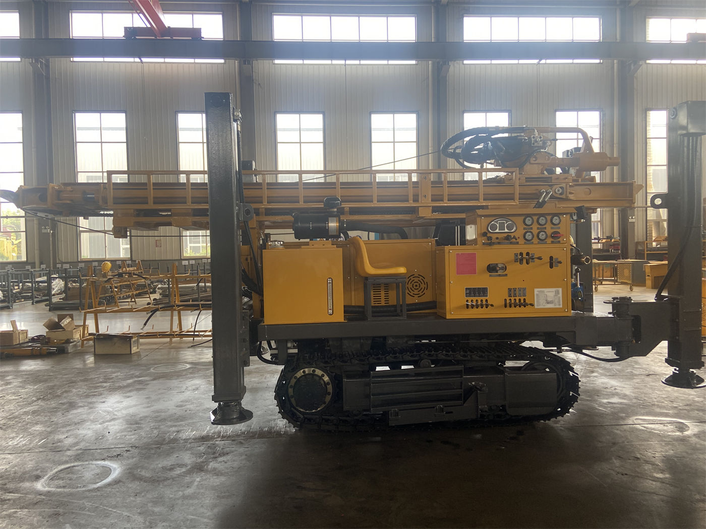
The mast type determines the mobilization method and site conditions. In the WR1000S model designation, S stands for telescopic mast. The materials explain its function as "reducing the overall machine profile in transport mode and maintaining the working height required for deep-hole construction in operating mode," thereby balancing loading, road passage, and 6 m drill pipe operation capability. It is necessary to distinguish clearly here: the telescopic mast changes the profile and height in both transport and operating states, but the materials do not state that it can replace verification of road width limits, height limits, and bridge load capacity.
Overall machine dimensions and weight are hard conditions for the same process. The WR1000S has an overall weight of approximately 17.8 T and dimensions of approximately 7.3 × 2.25 × 2.75 m; the WR1500S has an overall weight of approximately 28 T and dimensions of approximately 11.5 × 2.6 × 3.5 m. The two tonnage classes are not on the same order, and transport plans cannot be applied interchangeably. The materials also note that during transport, the flatbed truck load capacity, road width limits, height limits, and bridge load capacity must be confirmed.
Step 5: Supporting air supply and process route must be determined in advance, not added after work begins
Deep-hole and large-diameter projects have very high pressure and displacement requirements for air compressors. The WR1000S materials give a recommended working air pressure of 1.6–8 MPa and air consumption of 16–96 m³/min, and clearly state that "actual selection should be comprehensively determined based on the DTH hammer, hole diameter, hole depth, altitude, and rock hardness; insufficient displacement will directly affect impact and cuttings removal efficiency." In 1000 m-class deep holes, the transport distance for rock cuttings at the hole bottom is long, and inadequate cuttings removal can easily form sediment and cause repeated crushing, further increasing torque and energy consumption.
Regarding the process route, the WR1000S supports both mud rotary drilling and DTH hammer drilling: for soil layers, clay, sand layers, and gravel layers, mud, casing, and other wall protection methods can be used to first establish a stable hole section, then switch to the DTH hammer process after entering rock formations. For fractured zones, fissures, and air-leakage layers, the materials only state that "excessively fast advancement should be reduced, hole cleaning should be strengthened, and casing, foam, or other hole-stabilizing measures should be used as appropriate," without giving specific parameters or operating steps. When such hole sections are involved, the plan needs separate confirmation.
Step 6: The diesel-electric dual-power option must be judged separately and does not enter the drilling depth sequence
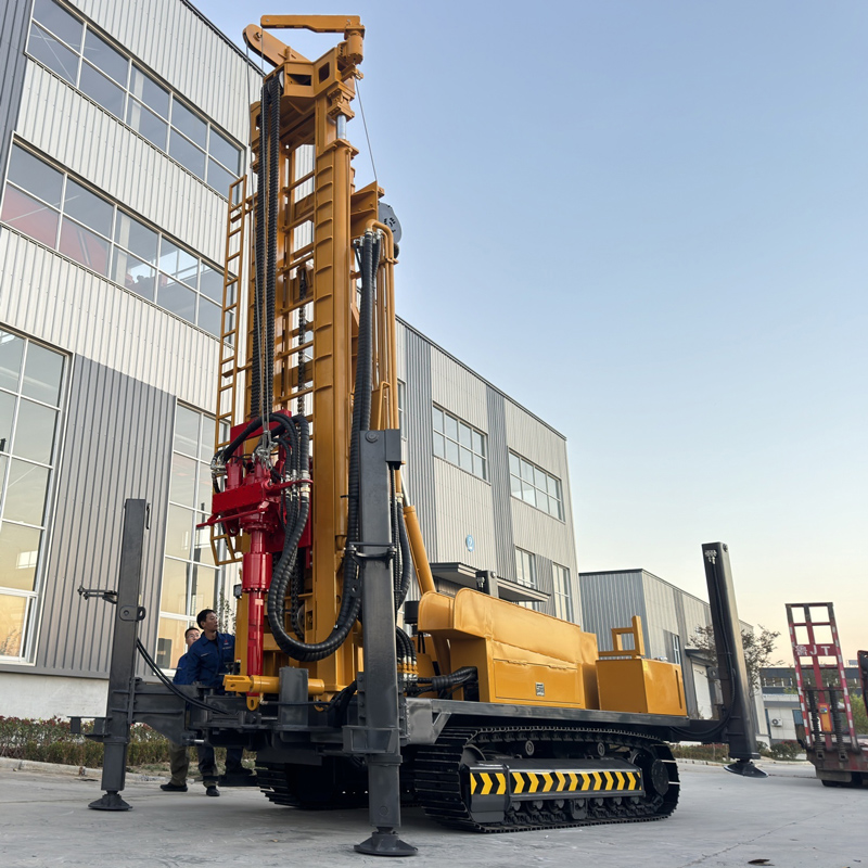
Another dimension of choice appears in the materials for 1200 m-class equipment. The power section of the WR1200SL lists both a 264 kW Cummins diesel engine and a diesel/electric dual-power configuration, with the qualification: "The final power, voltage, frequency, and starting scheme of the electric part should be determined according to the project power supply system." This indicates that diesel-electric dual power is a configurable power option, and whether to adopt it depends on the power supply conditions at the site, rather than being a natural extension of the drilling depth judgment.
Therefore, at this step, equipment classification and power scheme are two parallel lines of judgment: drilling depth, hole diameter, and drill string load determine the model tier; power supply conditions determine whether to choose diesel or dual power within the same tier. The materials do not provide an operating cost comparison of the two schemes, nor a list of applicable projects, so this part needs to be verified with the manufacturer during the selection stage.
Condensing the six steps into a sequence table
- First divide the target well depth into two columns: routine depth and deepest value; do not directly use the equipment's maximum drilling depth in place of the design well depth
- After determining hole diameter and completion structure, recheck the well depth margin, because large hole diameters raise the overall machine load
- Verify drill string load using lifting force, axial pressure, and rotary torque, not the drilling depth value
- Drill pipe length and mast type determine mobilization method, connection and disconnection frequency, and site conditions
- Air supply pressure and displacement should be comprehensively determined based on DTH hammer, hole diameter, hole depth, altitude, and rock hardness
- Diesel-electric dual power is a branch of the power scheme, depends on on-site power supply conditions, and does not change the model tier
Matters requiring separate confirmation
The materials on this site do not provide price differences among equipment grades, nor footage data under different formation combinations. The quantitative matching relationship between lifting force and hole diameter and hole depth is likewise not covered by the materials, which can only provide the parameter items that need to be verified. During actual selection, the target aquifer depth, formation structure, completion design, transport route, and power supply conditions should be provided by the project party. The product materials on this site provide equipment capability boundaries and cannot replace hydrogeological evaluation and completion design. Specific configurations and optional items are subject to the contract and manufacturer confirmation.