












Disassembling for transport is not about making handling easier; it is about getting through the bottlenecks in the mine that the complete machine cannot pass. In the CR800UG documentation, the power pack, feed mechanism, drill rig base frame, oil tank unit and control unit are listed separately with reference weights, which means the equipment must be broken down into several pieces before entering the roadway, rather than appearing at the shaft collar as a complete machine.
To answer "why disassemble," two things need to be examined first: what the roadway end allows, and how heavy the equipment end is. The following uses only published product information; items not covered are noted separately.
Several bottlenecks the complete machine cannot pass underground
Underground mine space is limited by roadway width, height, turning radius and transport method. Equipment must not only have drilling capability but also accommodate transport and on-site layout. The CR800UG documentation describes the access methods for the split modules in specific terms: they can be sent to the work site in batches via inclined shafts, cages, mine cars or roadway transport systems.
Each of these access routes has its own limiting factors. Inclined shafts depend on gradient and track conditions, cages on the allowable dimensions and weight per trip, mine cars on loading length, and the roadway itself on width, height and turning radius. If any one of these is not satisfied, the complete machine cannot pass. The documentation does not give specific limits for these routes, so whether it can pass can only be checked against on-site measured dimensions.
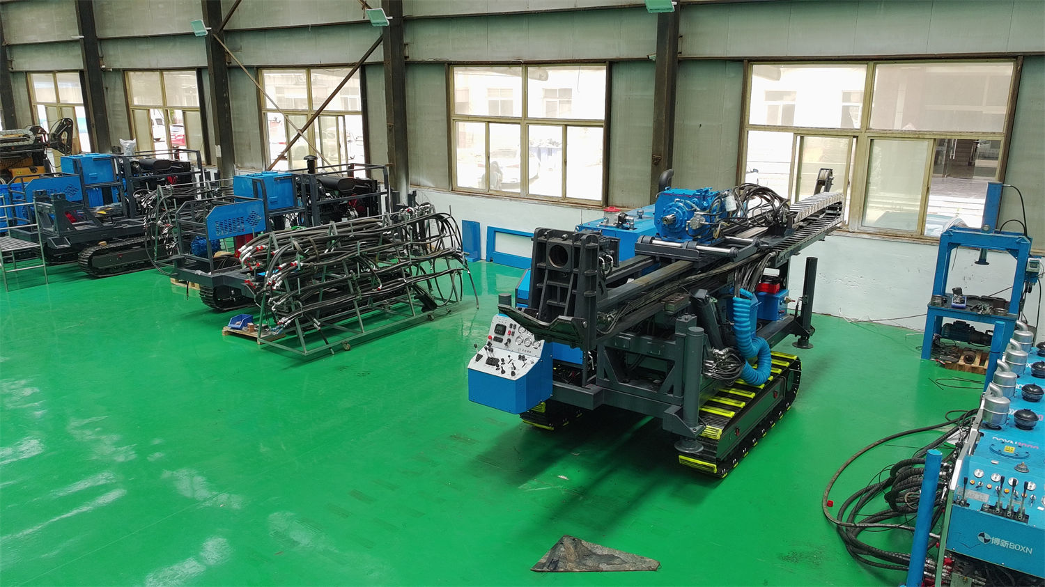
Reference weight of each module
After the complete machine is disassembled, the weight of each piece generally falls within the same order of magnitude, which directly determines the choice of lifting and transport methods.
| Module | Reference weight |
|---|---|
| Power pack | 240 / 270 kg |
| Main feed mechanism | 130 kg |
| Drill rig base frame | 120 kg |
| Oil tank unit | 120 kg |
| Control unit | 90 kg |
One point in the documentation needs clarification: in the original parameters, the "control unit weight" has two different markings—130 kg in the control unit table and 90 kg in the main module weight summary. This article retains both as originally marked; the final supply configuration and actual weight should be based on formal technical confirmation documents.
The power pack is the heaviest piece
The power pack has a reference weight of 240 / 270 kg, making it the heaviest of the modules. Its corresponding power configuration is 22 kW × 3 or 30 kW × 2 motors, with a main system flow of 200 L/min and pressure of 210 bar. The power pack must be positioned underground and then combined with the other modules, so whether it can pass through a cage or inclined shaft on its own often determines whether the entire transport plan is feasible.
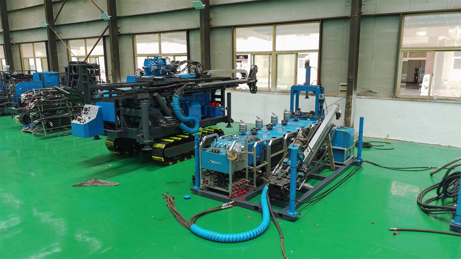
The choice of electric motor power is also related to the underground environment. Compared with diesel power, electric motors do not produce combustion exhaust at the drilling site, making them more suitable for underground mines that already have a stable power supply system. During actual configuration, the electrical scheme should be confirmed according to mine voltage, frequency, cable length and starting method. Standard motor configurations cannot be directly regarded as explosion-proof configurations; in coal mines, gassy mines or underground environments with combustible dust, motors, electrical control boxes, cables and protection systems with the corresponding explosion-proof rating should be selected in accordance with local mine safety regulations, and they must not be used directly in areas with explosion-proof requirements without confirmation.
After disassembly, it must be reassembled at the drilling site
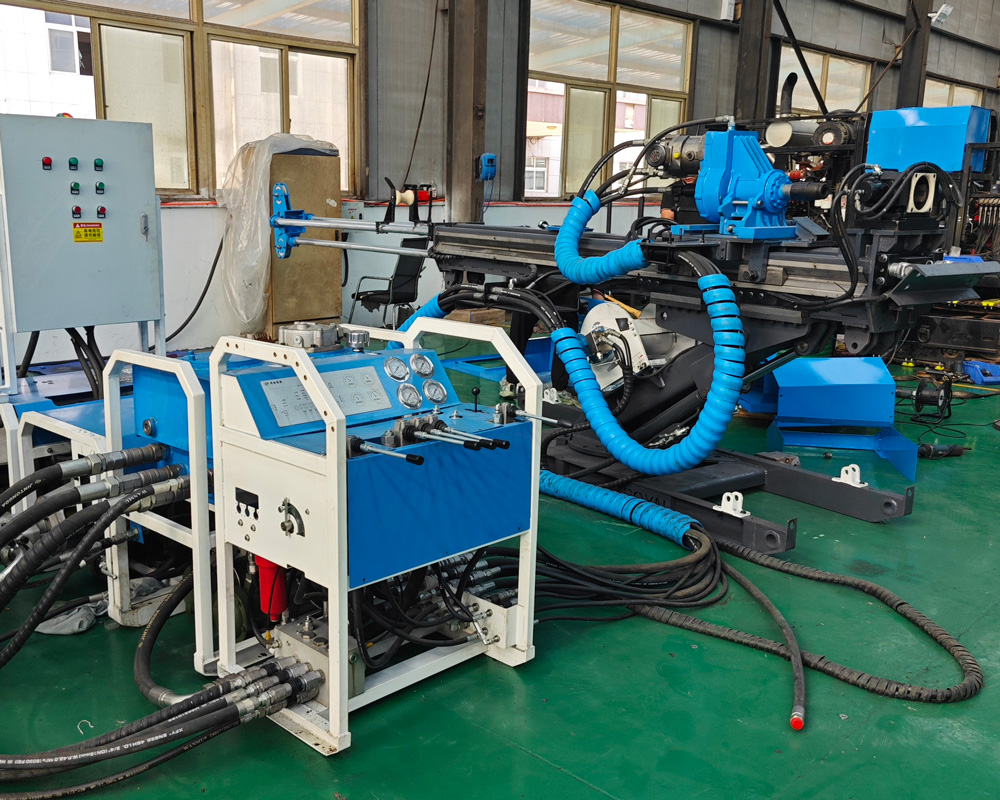
Split transport solves the access problem; next is completing the combined installation at the underground drilling site. This step also has site requirements: before equipment installation, the drilling site roof, ribs and floor support should be inspected; the drill rig base frame needs reliable fixing to prevent equipment displacement caused by drilling reaction forces; cables and hydraulic hoses should avoid transport routes and sharp rock walls.
The documentation also mentions that the modular design itself is intended to allow separately transported components to be reassembled on site. As for the time, personnel and special tools required for assembly, the documentation does not provide them and they need to be confirmed separately with the manufacturer.
Transport method is only one reason for splitting; there is also drilling direction
The CR800UG has different reference coring capacities in different drilling directions: at 90°, BQ 920 m, NQ 800 m, HQ 380 m; at 0°, BQ 600 m, NQ 400 m, HQ 200 m; at -90°, BQ 350 m, NQ 200 m, HQ 150 m.
Underground drilling often requires holes to be arranged in different directions from existing roadways: downward holes are used to verify deep orebody extension and faults or host rock changes, horizontal holes can directly control orebody thickness and continuity from crosscuts or haulage roadways, and upward holes can be used to verify mineralization above the roadway and roof structures. Different mines may define the positive and negative signs of angles differently; before formal construction, the on-site installation direction and design drawings should be taken as the standard. These differences in drilling depth by direction are issues encountered only after the equipment is positioned in the roadway, and they belong to a different stage from the transport method.
Several items still to be verified
- The allowable weight and dimensions of individual pieces for each on-site route (inclined shaft, cage, mine car, roadway); the documentation does not give limits.
- Which of the two markings for control unit weight matches the final supply.
- The time, personnel and special tools required for underground assembly.
- The electrical scheme corresponding to mine voltage, frequency, cable length and starting method.
- Whether the area has explosion-proof requirements, and the corresponding protection rating configuration.
Because actual geological conditions, downhole tools, drilling angles and operating methods vary, the final drilling efficiency, drilling depth and core recovery results should be based on on-site conditions. The above content is a compilation of information and does not constitute on-site construction or safety operation advice; manual verification should be carried out before procurement and use.