












Deep-hole core drill rig specifications usually have a dozen or so rows of parameters, ranging from drilling depth, torque, and hydraulic pressure all the way to engine displacement and electrical system voltage. After reading row by row and looking back, the only thing that is easy to remember is often the largest drilling depth figure. Taking the CR1600I on this site as an example, its parameter table lists a reference drilling depth of 2000 m for B size, 1500 m for N size, and 850 m for H size, a maximum torque of 4800 N·m, a main pump flow of 320 L/min and pressure of 31 MPa, a mud flow of 250 L/min and pressure of 7 MPa, a rope capacity of 1800 m, and a clamp through-hole of 150 mm. These values are not information at the same level, and it is clearer to process them in several groups when reading.
Group 1: Drilling depth should be read by size classification, not by taking the maximum value
In the CR1600I specifications, drilling depth is written in three rows rather than one: 2000 m for B size, 1500 m for N size, and 850 m for H size. The three figures correspond to reference capabilities under different drill rod sizes. The larger the size and the larger the hole diameter, the smaller the achievable depth. This is a conventional relationship in core drilling. Therefore, when seeing the figure of 2000 m, first confirm which size the project uses, and then look at the corresponding depth reference value.
In the model parameter table on this site, the "coreCapacity" column is also written as "BQ 2000 / NQ 1500 / HQ 850", consistent with the above three tiers. As for the actual achievement of these values under specific formations, hole deviation, and operating methods, the specifications do not provide condition descriptions, and this needs to be confirmed separately in conjunction with the project.
Group 2: Torque and the hydraulic system should be read together
Reading only 4800 N·m tells you the upper limit of the power head output. To judge whether this upper limit is supported in deep holes, the hydraulic system column must be brought in: main pump flow 320 L/min, pressure 31 MPa; auxiliary pump flow 160 L/min, pressure 23 MPa. The power head is driven through gears, with gear conversion ratios of 1:3 / 1:3, and a maximum speed of 1500 rpm. These values together explain the capability of the hydraulic source and the transmission configuration. The 4800 N·m does not exist in isolation.
When describing the hydraulic system, the specifications mention that during long-term construction, hydraulic oil cleanliness, filter pressure difference, and system temperature rise should be controlled. These three items are conditions on the user side. The parameter table only gives pressure and flow, and does not give the cycles or limits corresponding to these maintenance requirements.
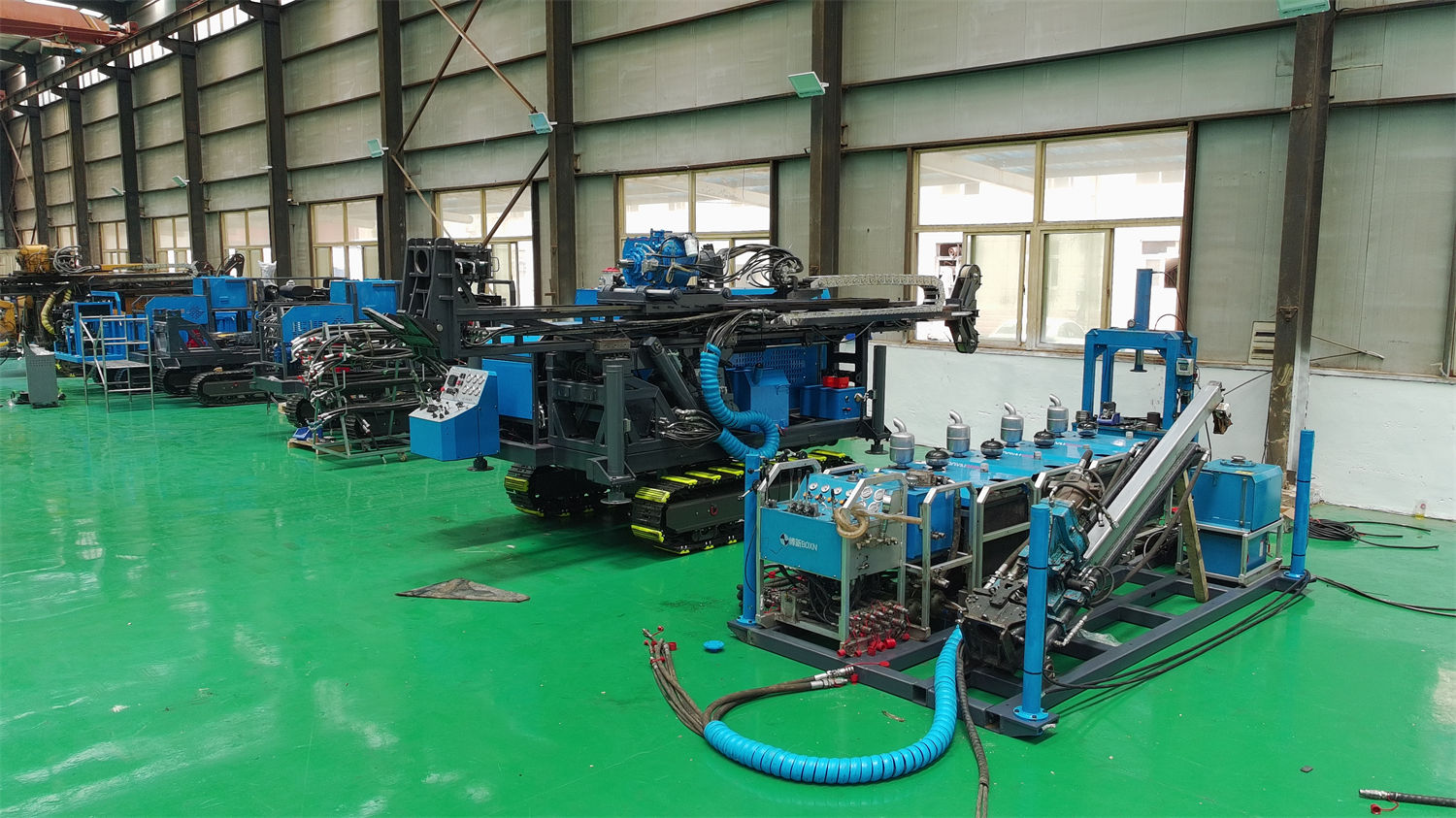
Items that should also be checked in the same column
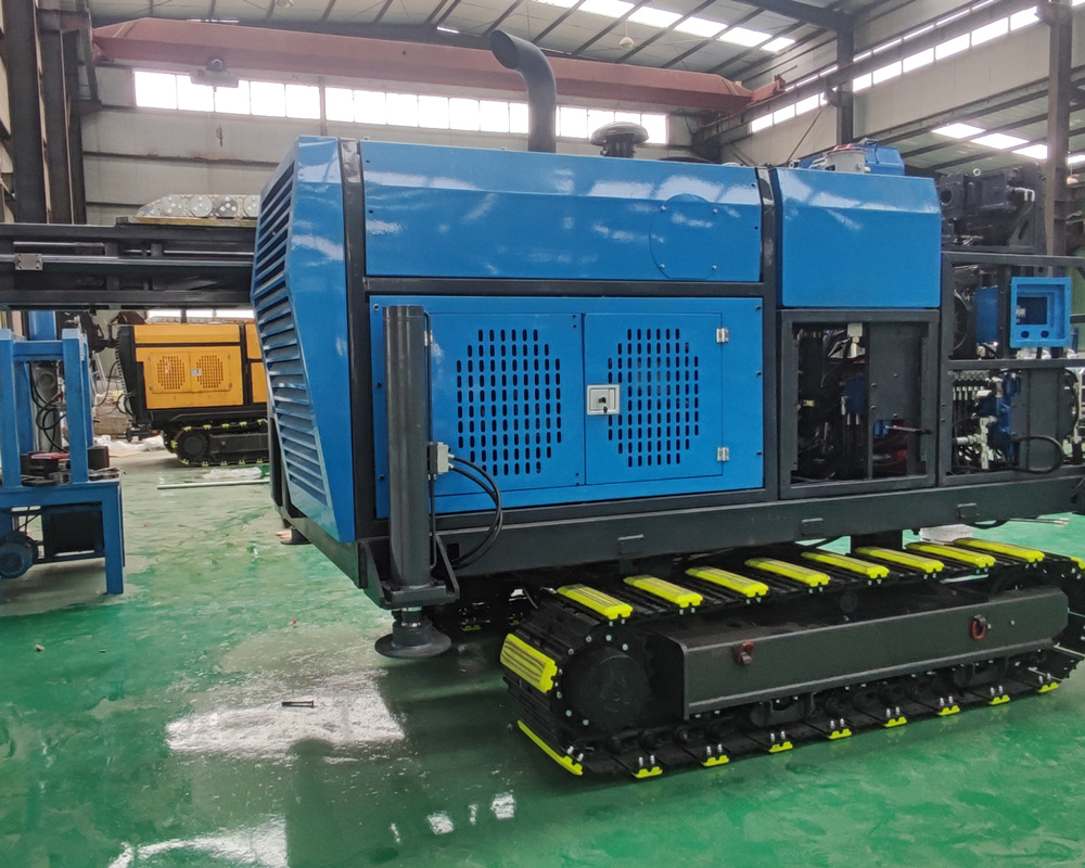
- Power assembly: Cummins 6CTA8.3, displacement 8.3 L, rated power 153 kW, rated speed 2000 rpm, 6-cylinder inline turbocharged, water-cooled.
- Cooling method: air cooling + water cooling, corresponding to the heat dissipation path under long-term continuous operation.
- Electrical system: 24 V, a basic value of the overall machine electrical configuration.
There is also a note in the specifications: the model title in the last column of the PDF power assembly table shows "BX1500T", while the other parameter tables on the same page correspond to BX1600T. This page only organizes the parameters provided in that column, such as 6CTA8.3, 153 kW, and 8.3 L, and does not make additional inferences about the model title discrepancy in the original specifications.
Group 3: Mud flow and winch rope capacity correspond to two deep-hole processes
One difference between deep holes and shallow holes is that the time and risk occupied by auxiliary processes in the hole both increase. In the CR1600I specifications, two sets of values fall exactly on this point.
The mud system has a flow of 250 L/min, pressure of 7 MPa, speed of 727 rpm, and power of 15 kW. The specifications state that it serves drill bit cooling, cuttings transport, and hole wall stability. In deep holes, the rock powder transport path is longer, and return water stability will change with hole depth and formation. Therefore, this set of values should be read together with drilling depth, rather than comparing magnitudes alone.
The winch system uses a 6 mm steel wire rope, with a rope capacity of 1800 m, a lifting force of 13.5 kN, and a lifting speed of 118 m/min. By placing rope capacity together with the three drilling depth tiers in the table below, the relationship between the 1800 m rope capacity and the B and N depth tiers can be seen.
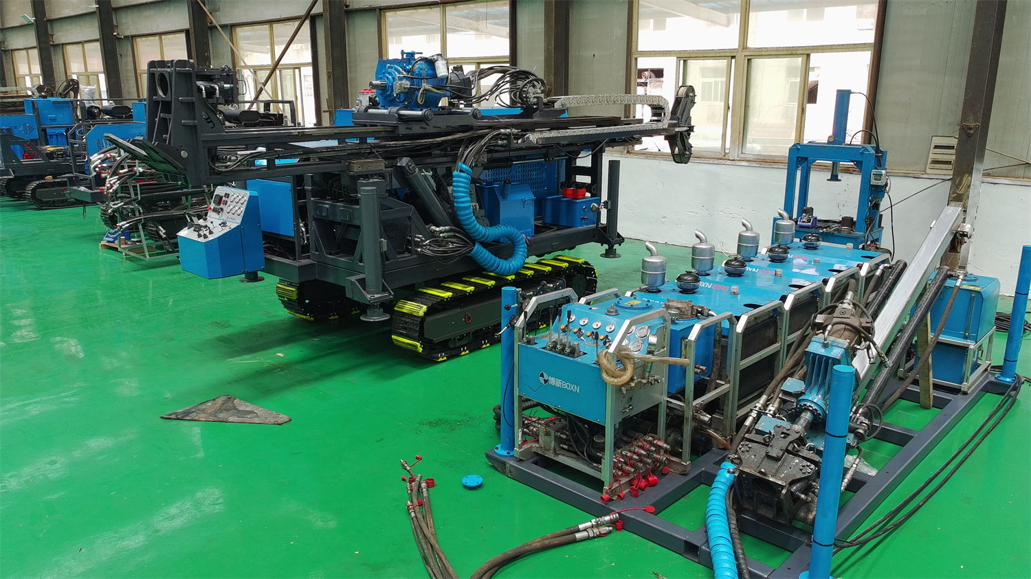
| Item | Parameter Value | Corresponding Process |
|---|---|---|
| B size reference drilling depth | 2000 m | Reference for wireline coring inner tube lifting distance |
| N size reference drilling depth | 1500 m | Reference for wireline coring inner tube lifting distance |
| H size reference drilling depth | 850 m | Reference for wireline coring inner tube lifting distance |
| Rope capacity | 1800 m | Determines the usable length of the steel wire rope |
| Lifting speed | 118 m/min | Affects auxiliary time per run |
The relationship between the 1800 m rope capacity and the 1500 m-class N size depth can be checked numerically. However, the specifications do not give steel wire rope wear, replacement cycles, or actual lifting times at different depths. These are matters on the user side that need separate confirmation.
Group 4: Feed, pull, and clamp through-hole are one set of load information
The mast and feed system column gives a feed stroke of 3.3 m, feed speed adjustable between fast and slow, feed force of 63 kN, and pull force of 185 kN. The model parameters on this site also record a pullback force of 185 kN, consistent with the pull force value. This set of values answers the margin questions for deep-hole drill string control and tool recovery, and should be read together with the drilling depth above.
The clamp part has a through-hole diameter of 150 mm, hydraulic clamping + wooden horse wedge-shaped self-weight anti-drop, and is suitable for drill rods NQ, HQ, PQ, NTW, and HTW. Two things should be distinguished here: the through-hole diameter determines the maximum size of drilling tools that can pass through, and the list of applicable drill rods determines the compatible drilling tool system. The specifications do not explain the drill string combination methods for these drill rods under deep-hole conditions, and this part is outside the coverage of the parameter table.
Drilling angle and the three depth tiers are two sets of conditions used separately
The CR1600I supports a drilling angle of 45°–90°, with a hydraulic telescopic mast and hydraulic side shift. Angle information corresponds to the drilling layout method and belongs to a different category from drilling depth and torque: drilling depth answers "how deep can it drill", while angle answers "in which direction to drill". In projects where the ore body attitude is inclined and multi-directional control is required, these two sets of values should be checked separately and cannot substitute for each other.
The specifications mention that deep projects can form spatial control through multi-directional drilling. This is a description of layout thinking. The specifications do not give calculation methods for specific angle allocation and hole spacing arrangement.
Which values are outside the specifications
The values that can be checked in the CR1600I specifications are concentrated in the columns for drilling capability, power head, mast feed, winch, clamp, hydraulic system, mud system, power assembly, and electrical system. The specifications also state that due to differences in actual geological conditions, downhole tools, drilling angle, and operating methods, the final drilling efficiency, drilling depth, and core recovery effect should be based on on-site working conditions.
According to the coverage of these specifications, the following items have no corresponding values and need to be separately verified with the manufacturer or project party: the relationship between torque and speed settings when constructing different hole diameters; the load check method for deep-hole drill string combinations; the treatment threshold for hydraulic system temperature rise exceeding limits; the inspection cycles for steel wire ropes, clamps, and drill rod threads; and the mud system adjustment plan for deep leakage and fractured aquifers. The parameter table gives the capability range on the equipment side, while process-side parameters need separate confirmation.