












Comparisons of deep-hole core drills are often reduced to a set of drilling depth figures. But what truly determines the progress of a deep-hole project is not how fast a single run can drill, but whether the in-hole operations can proceed one after another: the drilling tools are lowered into place, the core barrel is pulled up, the core is removed, and the tools are lowered again. In the published specifications of the CR1200I, several sets of figures fall directly on this chain, while some figures appear to address other matters but in fact still affect continuity.
Run Cycles: The Part That Is Truly Prolonged in Deep Holes
The operating rhythm of wireline coring is composed of runs. The deeper the hole, the higher the proportion of time in each run spent pulling the inner tube, removing the core, and re-deploying the inner tube. The CR1200I documentation lists two parameters together: wireline winch rope capacity of 1200 m, hoisting speed of 116 m/min, and hoisting force of 13.5 kN. Together, these three determine whether the auxiliary phase of a run can keep pace.
- Rope capacity corresponds to the depth over which the equipment can maintain wireline coring capability; the documentation specifies 1200 m, consistent with the reference drilling depth for N size.
- Hoisting speed affects the time required for a single inner tube retrieval. This value does not change with hole depth, but the number of runs accumulates as the hole deepens.
- Hoisting force corresponds to the resistance level of the wireline and inner tube in the hole. In deep-hole sections, contact between the drill string and the borehole wall will change this resistance.
Only by considering these three together can one understand why documentation for deep-hole coring equipment lists winch parameters separately rather than grouping them under overall machine power.
Drill String Load: Continuity Seen from the Clamping Through-Hole and Pulling Force
The most common trigger for interruption of in-hole operations is the drill string becoming stuck or insufficient lifting margin. In the CR1200I specifications, the clamp through-hole diameter is 150 mm, suitable for common drill rod systems such as NQ, HQ, PQ, NTW, and HTW, with hydraulic clamping combined with a wooden-horse wedge self-weight anti-drop mechanism; the feed force is 55 kN and the pulling force is 160 kN. These items correspond to load scenarios at different stages.
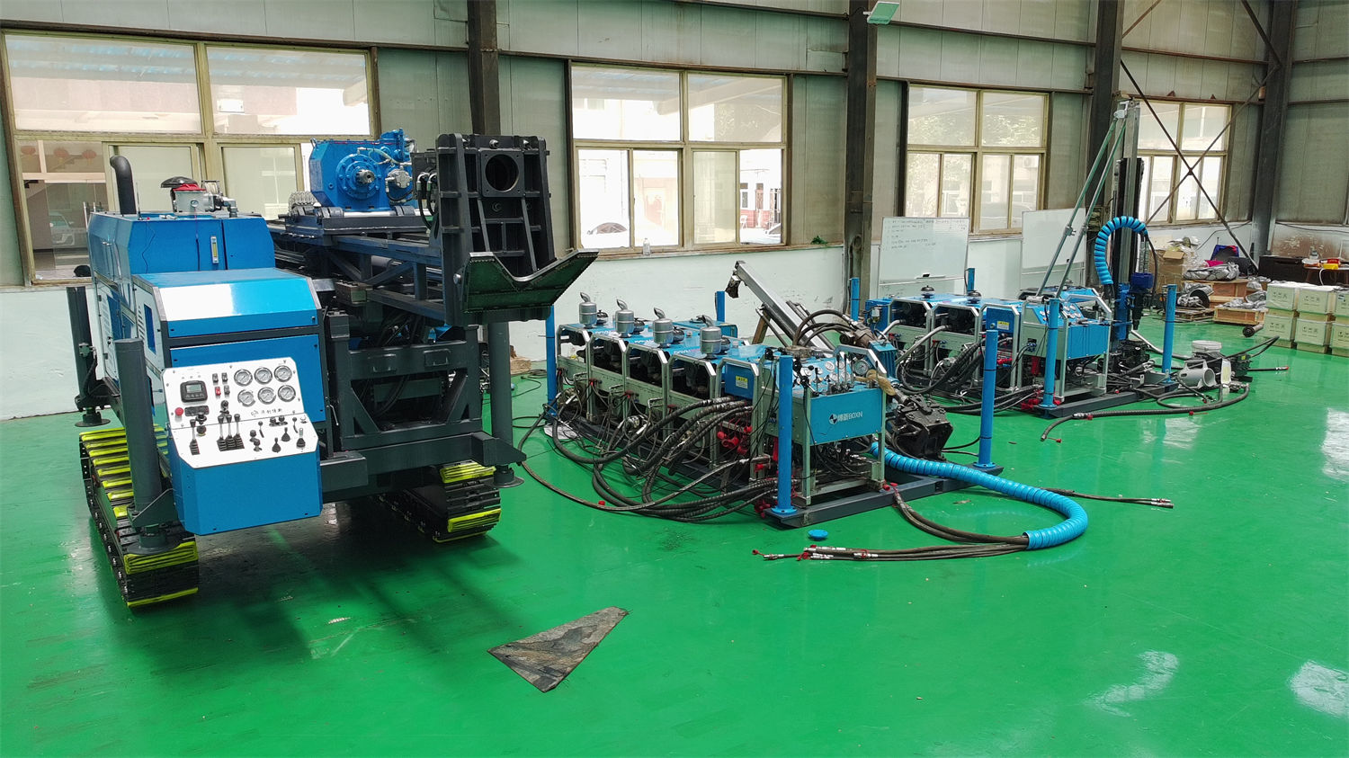
- The clamping through-hole and applicable drill rod systems determine whether this equipment can switch between different diameters of core drilling within the same hole without stopping the entire process to change specifications.
- Pulling force corresponds to the lifting margin when handling complex hole sections. The documentation gives 160 kN, but the actual usable value also depends on borehole wall friction, mud lubrication, and drill rod self-weight.
- The feed force of 55 kN corresponds to the axial thrust during normal drilling and must be used in conjunction with power head torque in hard rock.
These figures cannot by themselves serve as the basis for judging "what formations this equipment can drill into." The documentation itself also states that actual drilling efficiency, drilling depth, and core recovery results should be based on on-site conditions.
Power Head: Speed and Torque Switching Occurs When In-Hole Conditions Change
The CR1200I power head uses gear transmission, with a maximum torque of 2200 N·m, a maximum speed of 1500 rpm, and two gear ratios of 1:2.2 and 1:3.3. These two transmission ratios are not speed gears, but a redistribution between rotational speed and torque.
When rock formations alternate in deep holes, the same run may pass from fractured rock mass into intact hard rock. Gear switching and speed adjustment correspond to such in-hole changes, rather than being simple efficiency options. The documentation lists 2200 N·m as the maximum torque. This upper limit constrains the rotational capability the equipment can provide when resistance rises; it does not mean that every hole section uses the full value.
Hydraulics and Mud: Two Supports for Continuity
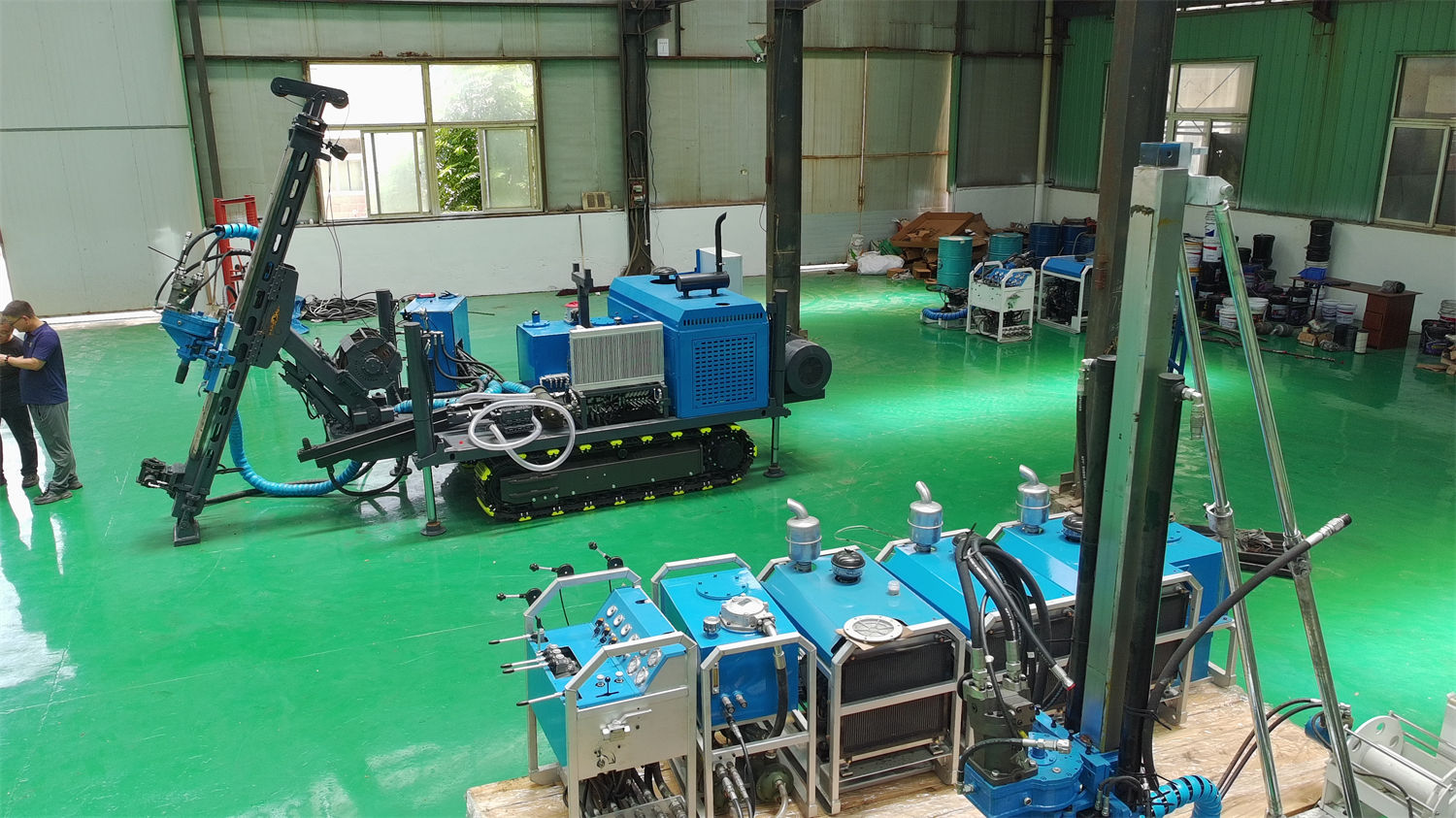
The CR1200I hydraulic system has a main pump flow of 300 L/min and pressure of 28 MPa, an auxiliary pump flow of 120 L/min and pressure of 21 MPa, and air cooling plus water cooling for cooling. The mud system has a flow of 150 L/min and pressure of 7 MPa. These two systems play different roles in deep holes.
- The flow and pressure of the hydraulic system support stable response of multiple actuators under long periods of high load. Deep-hole construction cycles are long, and the hydraulic system needs to maintain continuous operation under these conditions.
- The mud system is responsible for cuttings transport, drill bit cooling, and borehole wall stability. A flow of 150 L/min corresponds to circulation capacity. The documentation mentions that when facing developed fractures, unstable returns, and local loss, mud parameters should be adjusted according to in-hole performance, and plugging or staged wall protection measures should be adopted when necessary.
These two systems do not directly determine how deep a hole can be drilled, but their stability determines whether in-hole operations can proceed continuously as planned.
The Impact of Angle and Integrated Structure on Operational Continuity
The CR1200I supports drilling angles from 45° to 90°, uses a hydraulic side-shift mast and folding mast mounting method, has a feed stroke of 1.9 m, and features an integrated crawler structure. In exploration areas with continuous hole layout, these specifications directly reduce the time spent on repeated disassembly and reassembly and re-aligning holes.
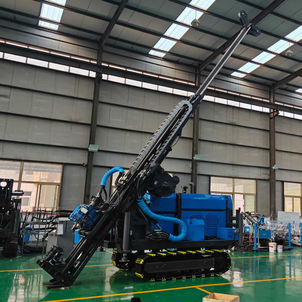
Deep exploration projects often arrange multiple boreholes in the same mining area, and some boreholes need to cut through ore bodies as inclined holes. The integrated crawler structure reduces repeated disassembly and reassembly among the power station, hydraulic modules, and mast system, but does not change the operational content of the borehole itself. The documentation does not provide the specific relocation time of this equipment between platforms in different mining areas; this part needs to be evaluated separately based on on-site roads and platform layout.
Which Figures Cannot Answer Continuity
The CR1200I specification table covers drilling capability, power head, feed, winch, clamping, hydraulics, and mud, but the following categories directly related to operational continuity are not provided in the documentation and need to be verified at the project level:
- Actual run length and drill bit life under different rock formation combinations, which depend on drilling tool selection and formation conditions.
- Hole deviation control methods for deep-hole sections, drill rod wear monitoring, and replacement cycles.
- Specific mud system formulations and plugging measures under different formations.
- On-site personnel's experience with wireline system operation and methods for handling complex hole sections.
The value of a deep-hole core drill ultimately lies not in the absolute value of any single parameter, but in whether the equipment specifications and actual in-hole conditions can form a continuous match. The published documentation of the CR1200I gives reference drilling depths of 1600 m for B size, 1200 m for N size, and 700 m for H size, as well as winch, clamping, hydraulic, and mud system parameters configured around deep-hole operations. These parameters can be used to check the equipment's configuration direction, but cannot replace on-site judgment of working conditions. The drilling plan, drilling tool assembly, and operating parameters for a specific project should be based on actual on-site conditions and the results of technical confirmation with the manufacturer.