












In core drilling in mountainous areas, whether a piece of equipment can drill and how fast it can drill can usually be roughly determined at the documentation stage; but whether a roadless drill site can start smoothly often depends first on answering several other questions: how the modules get up the mountain, where they are assembled, and whether dismantling and reassembling between two drill sites is worthwhile this time. The documentation for the CR600P 600 m portable modular fully hydraulic core drill presents these steps as verifiable module parameters and dismantling/assembly descriptions. Following these descriptions, this article lays out the procedures for a roadless drill site from site access to hole changeover.
Site Reconnaissance: First Distinguish "Reaching the Drill Site" from "Reaching the Foot of the Mountain"
The documentation states that the equipment's application scenarios include mountainous areas, forest areas, and roadless mining areas, and that drill sites are often distributed on hillsides, in gullies, in forest land, or on temporary platforms, with many locations lacking complete construction roads. This corresponds not to a single route but to two different endpoints: the location a vehicle can reach and the location where the drill needs to appear. The gap between the two is the distance over which modules must be moved.
Several types of information that need to be established during the reconnaissance stage include:
- The last location a vehicle can reach, as well as the elevation difference and approximate distance to the collar;
- Whether the transport route is a forest trail, a slope, or requires temporary clearing;
- Whether there is a temporary platform at the drill site that can be leveled, and whether its bearing capacity meets the requirements for assembly and drilling;
- Whether conditions such as hillside stability, rockfall, and rainy-season roads may change during the construction period.
The documentation only provides assessment directions; specific route lengths, maximum slope limits, and platform dimensions are not given as numerical values. This part can only be confirmed separately based on site conditions and cannot be inferred backward from equipment parameters.
Module Transport: Weight After Splitting Determines Transport Organization
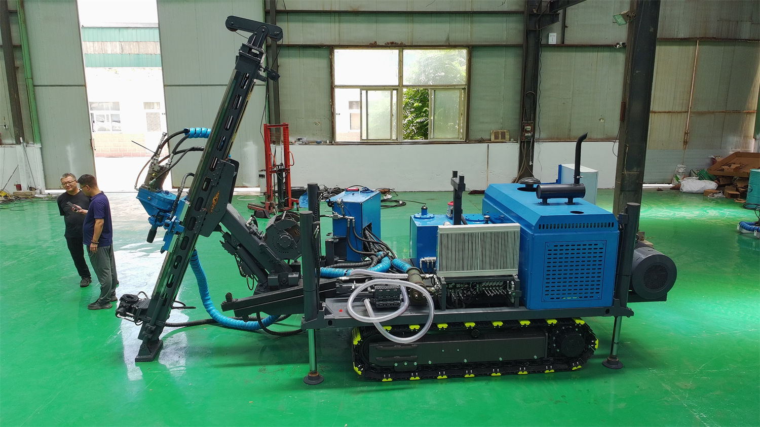
The significance of the modular structure lies in reducing the difficulty of moving individual modules. The reference module weights given in the documentation are as follows:
| Module | Reference Weight |
|---|---|
| Power unit | 180–260 kg |
| Operating unit | 125 kg |
| Hydraulic oil unit (including oil) | 140 kg |
| Mud unit | 86 kg |
| Total machine weight | 1200 kg |
This set of figures is the basis for transport organization: the power unit is noticeably heavier than the other units and often determines how much manpower or auxiliary equipment is needed to move a single piece. The documentation states that the equipment can be transported in batches to near the collar according to site conditions, but it does not give the external dimensions of each module or the maximum single-piece dimensions. Therefore, whether a given route section can be passed still needs to be verified separately based on actual dimensions and route cross-sections.
Power Type Will Change the Transport Checklist
The CR600P can use diesel or electric power. The diesel engine power requirement is ≥66 kW, and diesel engine brands can be Kubota, Cummins, Yunnei, or Yuchai; the electric option is a 22 kW × 2 motor combination. The two power types correspond to different transport contents and site conditions: the diesel option places more emphasis on independent power, while the electric option requires confirming in advance whether there is a stable power supply near the drill site and the actual method of supplying power to the drill site. The documentation does not explain the differences in module weight between the two options, so this item needs to be confirmed with the manufacturer.
On-Site Assembly: The 30-Minute Claim Depends on the Conditions for It to Hold
The documentation explicitly states that assembly work can be completed in as fast as about 30 minutes, while also explaining that the actual time required will be affected by transport distance, site conditions, personnel proficiency, and supporting equipment. For roadless drill sites, this time is closer to the segment of work after "all modules are already in place and the site is ready for assembly," rather than the total elapsed time calculated from when the vehicle stops.
After assembly is completed, the inspection items mentioned in the documentation include quick-change connectors, hydraulic lines, and structural connections; before inclined-hole drilling, the drill mast and base must be ensured to be stable. The CR600P supports drilling at 45°–90°, and the angle is selected based on orebody attitude. Therefore, the drilling angle for the hole must be determined at the assembly stage, rather than adjusted after drilling begins.
Drilling Stage: Several Sets of Parameters Related to Drill Site Organization
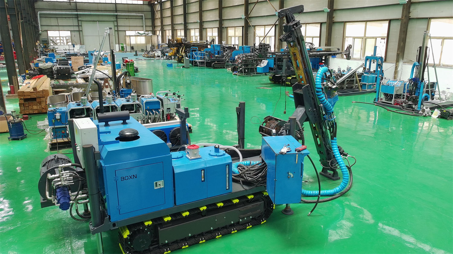
The drilling capacity of the CR600P is listed by specification: BQ reference drilling depth 760 m, NQ reference drilling depth 600 m, HQ reference drilling depth 280 m. Different specifications correspond to different drilling tools and run organization. How many holes are planned for a drill site and to what specification each hole is drilled will directly affect the frequency of hole changeover.
Other parameters more directly related to roadless drill sites include:
- Applicable drill rod length 1 / 1.5 m, meaning more rod connections than with long-rod options and more frequent auxiliary actions per unit of footage;
- Feed stroke 1.8 m, feed force 55 kN, pull force 100 kN;
- Maximum rotation speed of the power head 1200 rpm, maximum torque 780 N·m;
- Maximum clamping force of the clamp 120 kN, through-hole capacity 54–127 mm, hydraulically clamped with pressure-loss protection design;
- Wireline hoist rope capacity 800 m (6 mm wire rope), lifting speed 116 m/min;
- Mud pump flow 90 L/min, pressure 3 MPa, hydraulically driven, mud mixer mixing capacity 1.2 m³/min.
These values each constrain different steps. For example, the combination of short drill rods and a 1.8 m feed stroke determines the rhythm of each feed and rod connection; the 800 m rope capacity is a capacity condition for wireline coring operations, and whether it can be fully used in practice still depends on hole depth, drilling tool assembly, and site working conditions. The documentation also clearly states that the final drilling efficiency, drilling depth, and core recovery results should be based on site working conditions.
Hole Changeover Organization: The Number of Dismantling and Assembly Cycles Is the Variable in This Problem
When exploration line drill sites are relatively scattered, the proportion of auxiliary work during hole changeover increases. The value of the modular structure is reflected here: the equipment can be split into several units and moved separately, reducing dependence on road construction and large vehicles. However, each hole changeover means one dismantling, transport, and reassembly cycle, and the number of modules determines the workload of a single hole changeover.
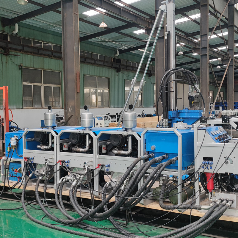
The documentation does not give the complete dismantling time, nor does it give the correspondence between unit transport distance and time. Therefore, the statement that "rapid dismantling and assembly can significantly reduce auxiliary work for hole changeover" can only be understood as a structural advantage. How much time is saved for a specific project needs to be calculated on site based on transport distance, slope, and personnel configuration.
The daily inspection items mentioned in the documentation can be incorporated into the intervals between hole changeovers: hydraulic oil, filters, wire rope, clamps, and mud pump; the broken wires, flattening, wear, and spooling condition of the wire rope; and timely troubleshooting when abnormal temperature rise, leakage, or changes in pull-out resistance occur. These inspections are distributed in the window period between two drill sites and are less troublesome than stopping during drilling to handle them.
Beyond the Documentation: Five Conditions That Require Separate Confirmation
The publicly available documentation for the CR600P covers drilling depth, angle, power, hydraulics, feed, clamping, hoisting, mud, and module weight, but the following types of information do not appear in the documentation and are parts that must be separately established when organizing roadless drill sites:
- The external dimensions of each module and the maximum single-piece dimensions, used to determine whether specific road sections can be passed;
- The differences between the diesel option and the electric option in module weight and the number of transport units;
- The complete dismantling time, as well as the actual assembly time under different transport distances;
- The dimensions, slope, and bearing requirements of the temporary platform;
- Expected drilling efficiency for the specific project's geological conditions, downhole tools, and drilling angle.
Separating the parts supported by the documentation from the parts beyond it is a fundamental skill in organizing this type of drill site. The former can be scheduled in advance, while the latter can only be taken as questions to the site or confirmed with the manufacturer, and should not be replaced by adjacent figures in the parameter table.