












Mobilization preparation for deep-hole projects in remote mining areas is rarely a matter of filling in whatever is missing. What truly holds up progress is sequence: if lifting conditions are not defined, modules can only be stacked at the foot of the mountain when they arrive; if the power plan is not defined, it is impossible to say how much mud material to prepare; if there is no baseline in-hole data set, once deep-hole drilling begins, changes in pump pressure cannot be judged as a trend or an isolated event. The published CR1200P information describes the equipment side in considerable detail, so this article follows its module weights, power configuration, drilling capacity, and in-hole parameters to lay out the order in which pre-mobilization items should be addressed.
Stage 1: First confirm access, lifting points, and the platform; do not discuss drilling first
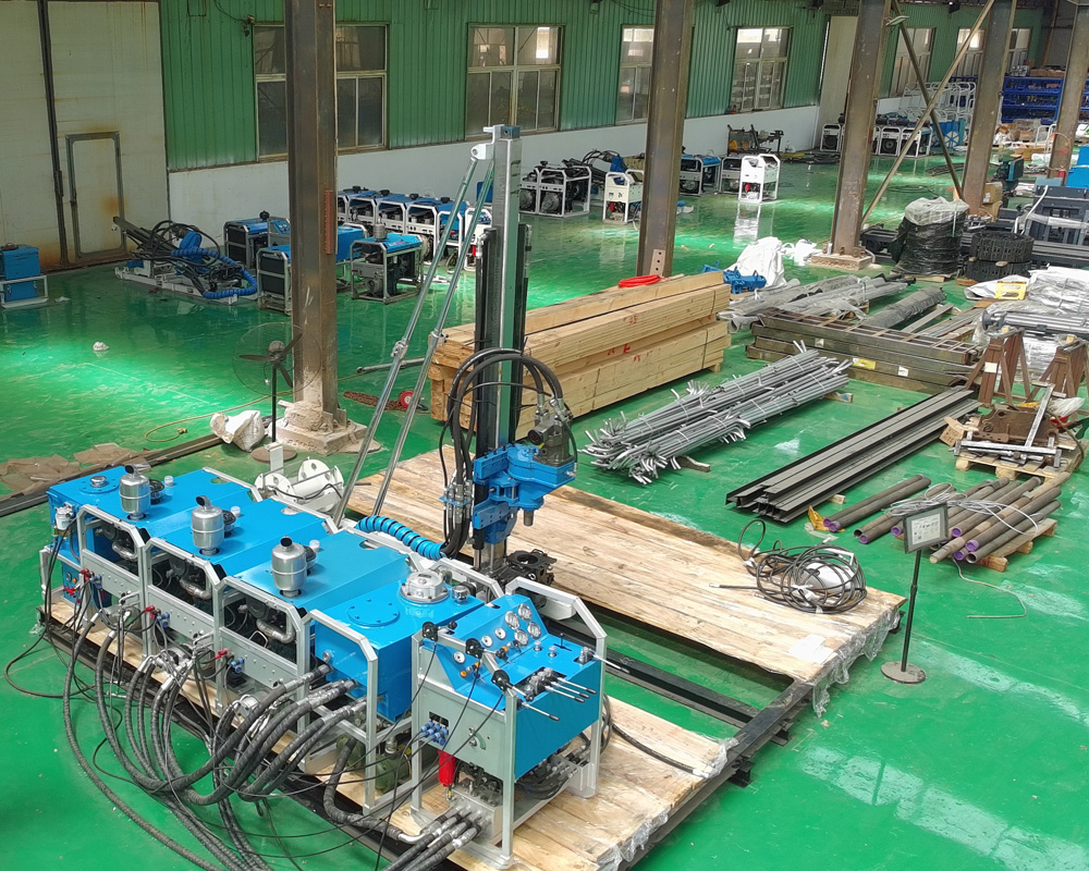
The CR1200P is positioned as a 1200 m-class portable modular full-hydraulic core drill, with reference drilling depths of 1200 m for NQ, 1500 m for BQ, and 700 m for HQ, and a drilling angle of 45°–90°. For these capabilities to be realized, the prerequisite is that the equipment can reach the hole location. The published reference module weights are: power unit 180–260 kg, control unit 160 kg, hydraulic oil unit (including oil) 160 kg, and mud unit 210 kg, with a total weight of 1880 kg. Module weight determines the specifications for single-piece transport and lifting; access load-bearing capacity, turning radius, and lifting point positions should be set according to the heaviest piece, not the average.
The platform must also be able to accommodate modular placement by zone. The significance of a modular structure is that it can be mobilized in batches, but placement determines assembly order and also determines which pieces are removed and whether rearrangement is needed when moving to the next hole. If any of the three—access, lifting points, and platform—is undefined, subsequent inventory work has no basis.
Stage 2: Inventory by module, then verify the power plan
After modules arrive, the first task is not assembly but inventory. The power unit, control unit, hydraulic oil unit (including oil), and mud unit are the four categories listed separately with weights and forms in the published information. During inventory, they should be checked one by one against the transport list, with particular attention to whether the hydraulic oil unit is counted in its oil-filled state; otherwise, the lifting load will be underestimated.
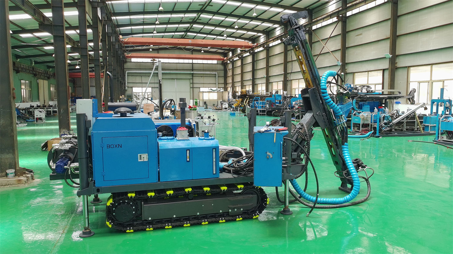
The power form must be decided at the same stage. The CR1200P can use diesel power or an electric option: the diesel engine power requirement is ≥147 kW, with options including Kubota, Cummins, Yunnei, and Yuchai; the electric configuration is 30 kW × 4, with speeds of 3000 / 1450 rpm. Remote field projects rely more on independent power and fuel security, and only fixed platforms with a stable power supply are suitable for considering electric power. This step affects fuel reserve volume, cable or power supply organization, and also feeds back into the transport list, so it should not be deferred until after assembly.
Stage 3: Assembly and item-by-item inspection; interfaces require more verification than external appearance
After module assembly, hydraulic interfaces and mechanical connections must be checked against the documentation; this point is explicitly included in the pre-drilling precautions in the published information. The CR1200P hydraulic system parameters are: main pump flow 250 L/min, pressure 25 MPa; auxiliary pump flow 10 L/min, pressure 17 MPa; main oil tank 250 L; control mode is manual plus pilot-operated; cooling is water-cooled or air-cooled. The relatively large hydraulic flow is necessary support for continuous deep-hole operation, but it also raises the requirements for hydraulic oil filtration, temperature control, and high-pressure line maintenance. Interface inspection during assembly serves this step.
On the mechanical connection side, the chuck and winch should also be checked together. The chuck is hydraulic, with a maximum clamping force of 130 kN and a through-hole capacity of 54–127 mm; the wireline winch has a rope capacity of 1400 m (6 mm wire rope), an empty-drum lifting force of 14.5 kN, a full-drum lifting force of 5.6 kN, and a lifting speed of 116 m/min. In deep holes, the inner tube lifting distance is long and the wire rope is used frequently, so wire rope inspection and replacement records should be established during assembly, with broken wires, wear, indentations, and rope-end connections included in periodic inspection items.
Stage 4: Power, water, and mud materials—three items must be decided together
The consumption of water and mud materials depends on which process is used and how deep the hole is drilled, and these two points are related to the power plan, so they are handled at the same stage.
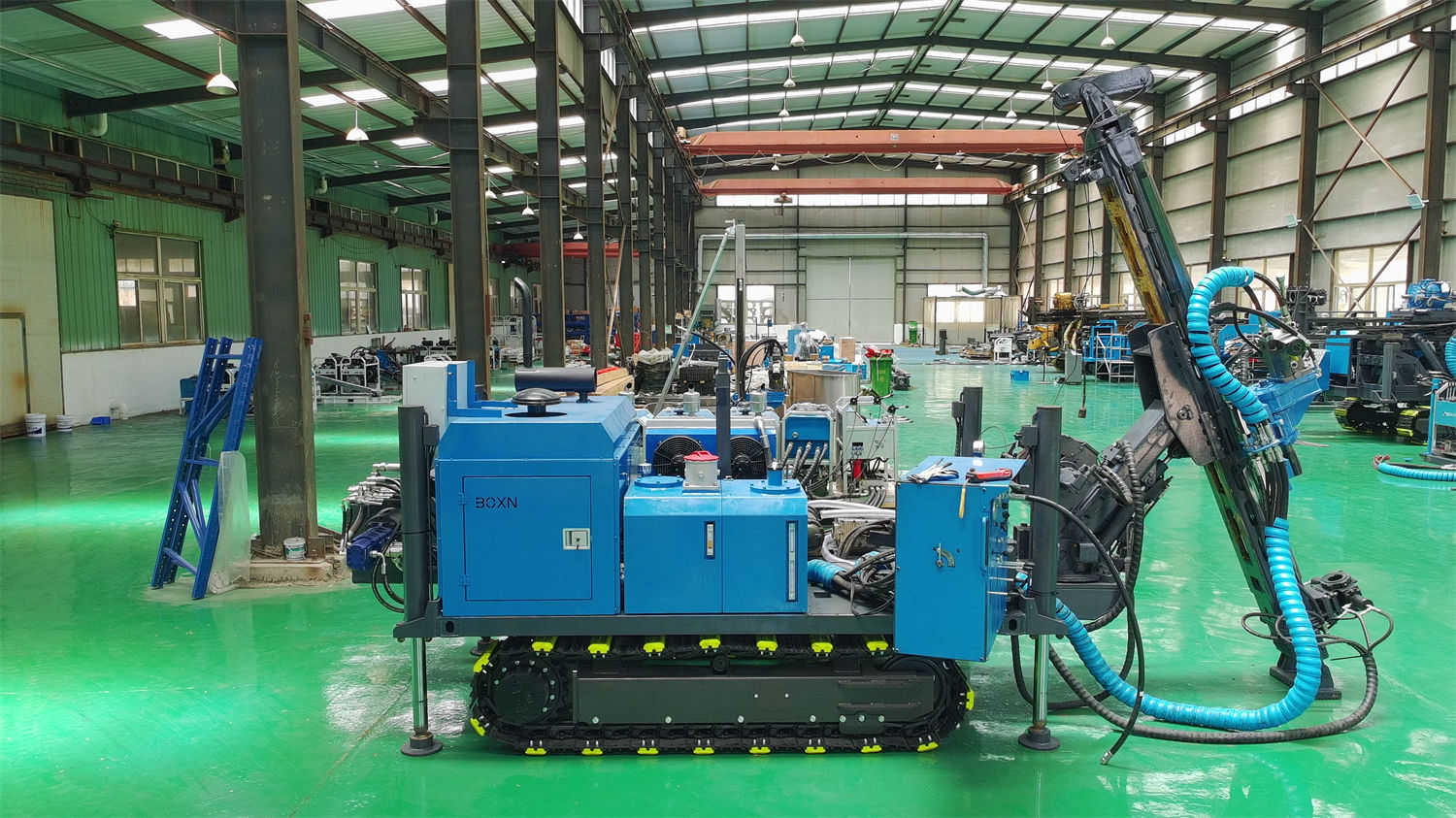
For the mud unit, the CR1200P is equipped with a plunger high-pressure pump, hydraulically driven, with a mud flow of 150 L/min and mud pressure of 7 MPa; the mud agitator is also hydraulically driven, with an agitator speed of 1500 rpm and a mixing capacity of 1.2 m³/min. In deep holes, cuttings must be carried over long distances, and mud simultaneously provides cooling, lubrication, and wall protection. When encountering deep leakage, water-bearing fractures, or broken zones, mud properties must be adjusted according to return water and pump pressure changes; therefore, material reserves cannot be converted using shallow-hole experience.
For power, the diesel option requires fuel preparation for a model of ≥147 kW, while the electric option requires power supply organization for 30 kW × 4. The feed system parameters are: feed stroke 1.8 m, thrust 67 kN, pull-up force 130 kN; the rotary power head has a maximum speed of 1500 rpm, maximum torque of 1360 N·m, maximum applicable drill rod diameter of 114 mm, and the power head supports swing or side shift, with applicable drill rod lengths of 1 / 1.5 m. These values cannot stand alone in a table; they are determined together with drill rod reserves and the spare parts list.
Spare parts, in particular, must be arranged early in remote mining areas. The published information explicitly states that common seals, filters, quick-change couplings, wire rope wear parts, drilling tools, and mud materials should be prepared on site, and that regular maintenance plans should be established for power, hydraulics, winch, and chuck. The time cost of waiting for parts is often higher than the cost of the parts themselves.
Stage 5: Pre-drilling in-hole conditions require a baseline data set
Before formal drilling begins, the published information requires confirming platform stability, drilling azimuth, drill rod reserves, and water and power supply. In addition to these items, a recording baseline for in-hole data should also be established. The CR1200P can drill within a range of 45°–90°, and after entering the deep-hole stage, torque, pump pressure, return water, and pull-out resistance must be continuously recorded, with trend anomalies addressed promptly.
A pull-up force of 130 kN does not mean in-hole problems can be solved by pulling. For 1200 m-class boreholes, controlling hole deviation, maintaining borehole wall stability, and reducing drill rod friction are more important than simply increasing pull-up force; if pull-out resistance continues to increase, circulation, pull-out inspection, or borehole wall treatment should be carried out promptly. After entering a fault zone, core breakage, abnormal pump pressure, reduced return water, or borehole wall caving may occur; at this point, mechanical impact should be reduced, run length shortened, and circulation anomalies addressed promptly. Severe leakage must be judged in conjunction with casing, plugging, or staged wall protection, rather than pursuing penetration rate alone.
| Stage | Items to address | Corresponding parameters or basis |
|---|---|---|
| Access and lifting | Access load-bearing, turning, lifting points, platform zoning | Reference module weights 180–260 kg, etc.; total weight 1880 kg |
| Inventory and power | Module inventory, selection of diesel or electric plan | Diesel engine ≥147 kW; electric 30 kW × 4 |
| Assembly and inspection | Hydraulic interfaces, mechanical connections, wire rope records | Main pump 250 L/min, 25 MPa; rope capacity 1400 m |
| Power, water, mud | Fuel or power supply, water source, mud materials, spare parts | Mud 150 L/min, 7 MPa; mixing capacity 1.2 m³/min |
| Pre-drilling | Platform, azimuth, drill rod reserves, in-hole baseline records | Torque 1360 N·m; pull-up force 130 kN; angle 45°–90° |
Values not covered by this site's information and requiring separate confirmation
The following categories of items have no corresponding values in this site's CR1200P information and must be confirmed separately at the project level: specific road width, slope, and bridge load rating required for mobilization; specifications and operating standards of local lifting equipment; the impact of water supply distance, water source yield, and water quality on mud preparation; compliance requirements for fuel storage and transport; and on-site communication and emergency evacuation arrangements. These should be confirmed through project site surveys and local conditions and cannot be derived from equipment parameters.
In addition, because actual geological conditions, in-hole tools, drilling angles, and operating methods vary, the final drilling efficiency, drilling depth, and core recovery results should be based on actual site conditions.