












Target well depth is the first condition obtained, and it is also the easiest to mistake directly for the selection conclusion. In actual judgment, the depth figure only determines the starting point of the equipment tier; several later conditions will push it up or pull it down: hole diameter and completion structure determine drilling tool load, and the load returns to lifting force and torque; drill pipe length and mast type determine the procedure, not just transportation; air supply and process route must be decided in advance and cannot be added after drilling starts. The following expands a feasible judgment sequence, with each step using only the values and descriptions published on this site, and indicating which questions the materials do not answer.
Step 1: Break the target well depth into "must drill" and "may drill"
The well depth in design documents is usually not a single point but two values: the depth that must pass through the main aquifer, and the margin that may be added due to formation changes. The former determines the lower limit of the equipment's drilling depth, while the latter determines whether to leave room by moving up one tier. The maximum drilling depth of this site's 1000 m class truck-mounted direct mast water well drilling rig WRT1000 is 1000 m. If the target aquifer depth plus margin is already close to or exceeds this figure, it should not be treated as the only candidate, and the 1200 m class model should also be considered.
This step does not require determining the model first. First determine two things: the depth range of the target aquifer, and whether the project can still accept changing equipment or design after exceeding the design depth. The materials do not include aquifer judgment methods; this part needs to be provided by hydrogeological data.
Step 2: Hole diameter and completion structure will reversely change the depth judgment
Well depth and hole diameter are not two independent conditions. The drilling diameter of the WRT1000 is 105–800 mm. For the same machine within this range, as the hole diameter increases, the drilling tool load in the hole, air compressor demand, and casing weight will all rise simultaneously. Therefore, for the same target well depth, equipping small-diameter well pipe and large-diameter well pipe imposes different requirements on the equipment tier.
Completion structure is also a variable. Whether casing is run, how long the screen section is, and whether a water-stop section is set will all change the hole section actually needing to be drilled and the drilling tool assembly. The output of this step is not a depth figure, but a set of combined conditions of "well depth + well diameter + completion structure." The materials do not include the well depth upper limit corresponding to each hole diameter; this part must be confirmed with the manufacturer.
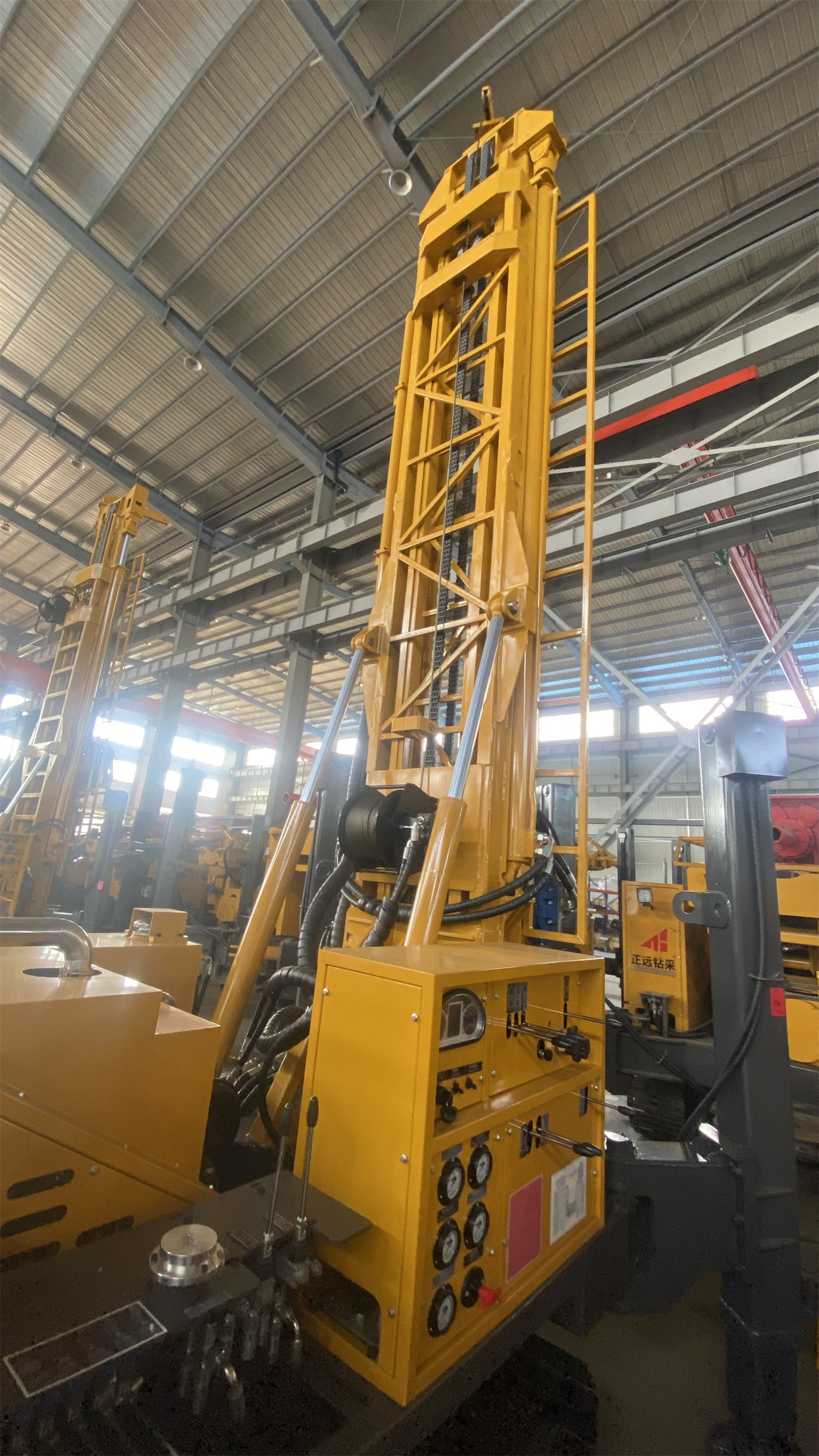
Step 3: Use lifting force and torque to check drill string load, not drilling depth
Drilling depth is only one expression of drill string length. What actually presses on the equipment is the self-weight of the drill pipe, casing weight, and borehole wall friction. The 51 / 52 T lifting force and 20000 / 10000 N·m dual-condition rotary torque given for the WRT1000 are two sets of values used to check such loads. At 1000 m class hole depth, the weight of drill pipe and casing will increase significantly, and insufficient lifting force will directly limit tripping and casing operations.
Torque corresponds to resistance during rotation. In the WRT1000's 70 / 140 r/min two-speed configuration, the low-speed gear corresponds to higher torque and is suitable for large-diameter, hard rock, and high-friction hole sections; the high-speed gear is suitable for stable formations with lower resistance. These two torque values cannot simply be understood as two speed gears; they correspond to load conditions in different hole sections.
At this point, the basis for judgment changes from "can it drill" to "when drilling to the target depth, can the drill string be lifted and rotated." The materials give the upper limit of equipment capability, not the actual load of a specific well; the project side needs to calculate it independently according to the planned drilling tool assembly.
Step 4: Drill pipe length and mast type determine the procedure
The WRT1000 has a feed stroke of 7 m, can use 3 m or 6 m drill pipes, and recommends a drill pipe diameter of 114 mm. The 6 m drill pipe is suitable for long-cycle deep hole construction and can reduce the number of pipe connections; the 3 m drill pipe is more suitable for sites with limited space, transportation, or manual operation conditions. The same machine equipped with different length drill pipes has a different procedure rhythm.
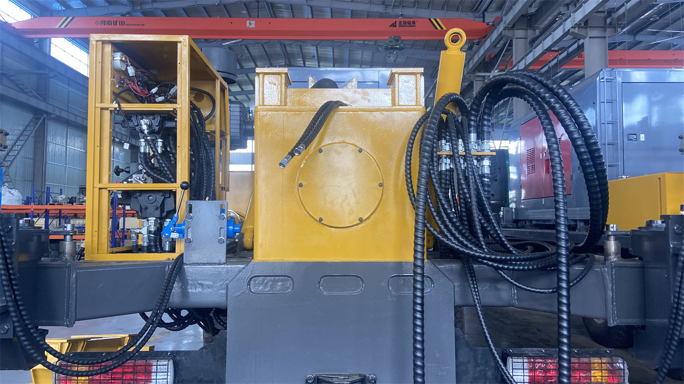
Mast type also affects the procedure. The WRT1000 uses a direct mast rather than a telescopic mast, with a more direct force path, favoring continuous deep hole operations; the overall transport dimensions are about 10.8 × 2.5 × 4.23 m. The 4.23 m transport height means that before entering the site, road height limits, bridges, overhead lines, and factory gate openings must be verified. The conclusion of this step usually falls on construction organization, not equipment capability.
Step 5: Supporting air supply and process route must be decided in advance
The recommended working air pressure for DTH down-the-hole drilling of the WRT1000 is 1.65–8 MPa, with air consumption of 16–96 m³/min. For 1000 m class deep holes and large-diameter hard rock, the pressure and displacement requirements for the air compressor are relatively high. During selection, a comprehensive judgment should be made based on DTH hammer specifications, hole diameter, hole depth, altitude, and rock hardness, and rated pressure alone should not be the only basis.
The process route also involves the treatment method for the upper hole section. In soil, clay, sand, and gravel layers, the WRT1000 can use mud rotary, casing, or other hole stabilization methods; after entering relatively intact hard rock, medium and high-pressure DTH hammers can be configured for DTH drilling. Once hole collapse, diameter reduction, or casing problems occur in the upper hole section, the risk and treatment cost of subsequent deep hole construction will rise. Therefore, the process switching point should be determined before drilling starts.
Step 6: Use supporting conditions to cross-check the judgment from Step 1
After completing the previous five steps, return to the initial target well depth and see whether it needs correction. Supporting conditions that need to be checked together include: whether the tonnage of the dual auxiliary winches can meet the handling needs of the DTH hammer, drill pipe, casing, and air hose; whether the cooling, air filtration, and fuel systems of the 194 kW diesel power can adapt to on-site dust conditions; and whether the approximately 26 T weight of the whole machine can be borne by the access road and platform.
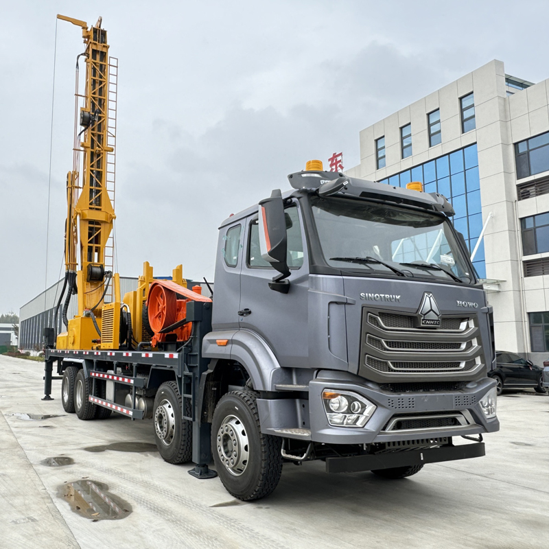
Consolidate these items into a checklist, in the following order:
| Judgment Step | Published Conditions Used | What This Step Answers |
|---|---|---|
| Target well depth breakdown | Aquifer depth range and margin | Whether it is necessary to enter the 1000 m class or above |
| Hole diameter and completion structure | 105–800 mm hole diameter range | Whether drilling tool load changes at the same depth |
| Drill string load verification | 51 / 52 T lifting force, 20000 / 10000 N·m torque | Whether tripping and rotation can be completed at the target depth |
| Drill pipe and mast | 7 m feed stroke, 3 m or 6 m drill pipe, direct mast structure | Whether the procedure rhythm and relocation conditions are acceptable |
| Air supply and process | 1.65–8 MPa air pressure, 16–96 m³/min air consumption | Whether the plans for hard rock sections and upper loose sections can connect |
| Supporting condition cross-check | Dual auxiliary winches, 194 kW power, approximately 26 T whole machine | Whether the originally determined well depth and equipment tier still hold |
Project-side calculations that this sequence cannot replace
The above six steps use only the parameters published on this site. What they can answer is the boundary of equipment capability, and they cannot replace the project side's hydrogeological judgment, drilling tool assembly calculation, and well completion design. The following items are not covered in the materials and need separate confirmation: target aquifer depth and thickness, well depth upper limit corresponding to each hole diameter, actual load under the planned drilling tool assembly, specific matching of air compressor and DTH hammer, specifications and quantities of casing and screen, and on-site road height limits and platform bearing capacity.
Treating target well depth as the only selection input usually exposes problems in the procedure or supporting links. Walking through these six steps in order first, then returning to the depth figure for final confirmation, saves more rework than determining the model first and then filling in conditions.