












For equipment selection in photovoltaic foundation pre-drilling, a common approach is to start with equipment parameters: how wide the hole diameter range is, how deep it can drill, and how much torque it has. But these values in the specification table do not by themselves point to a specific project. It is more practical to reverse the order—first look at the pile type, then derive hole diameter and hole depth from the pile type, and then check back against the equipment. Among the published PV390 parameters, the 80–600 mm hole diameter, 0–6 m drilling depth, 13,000 N·m torque, 120° mast pitch, dual-cylinder left-right swing arm, 50 cm front-rear telescopic compensation, 400 mm track shoe, and 35° gradeability each fall at different stages of the reverse-derivation chain and should not be lumped into a single statement.
Step 1: Pile type first separates hole diameter and hole-forming method
“Photovoltaic foundation pile” is not a single object. Within the same site area, support foundations, fence posts, and other shallow foundations do not have the same hole requirements. The materials state that the PV390 is used for photovoltaic support foundation pre-drilling, hole forming, and pile foundation construction with corresponding attachments, so the first step is to list the pile types appearing in the project by category.
- Conventional support foundations: usually correspond to smaller-diameter pre-drilling, with the hole diameter value subject to the design drawings
- Pile types requiring larger foundation holes: the upper limit of hole diameter given in the materials is 600 mm; holes beyond this range are outside the published scope of the PV390
- Fence posts and other shallow foundations: also within the applicable scope described in the materials, but the specific hole diameter is still determined by the design
At this step, what the materials can provide is the boundary of the hole diameter range—80–600 mm; what they cannot provide is which hole diameter should be used for a specific project. The correspondence between pile type and hole diameter comes from the design drawings, not from the equipment materials.
Step 2: Pile type also determines hole depth, and hole depth has a clear upper limit
The hole depth stated in the materials is 0–6 m, and it is clearly stated that the PV390 is positioned for photovoltaic pile foundations and shallow foundation projects, “rather than deep water well construction.” The significance of this limitation is more important than the number itself.
After sorting pile types by design depth, two situations arise: those with design depths within 0–6 m fall within the scope covered by the materials; for those with design depths exceeding 6 m, the available materials cannot support a conclusion as to whether the PV390 can handle them, and separate confirmation is required. No inference is made here as to whether “slightly exceeding the limit is acceptable,” because the original materials do not provide a margin explanation.
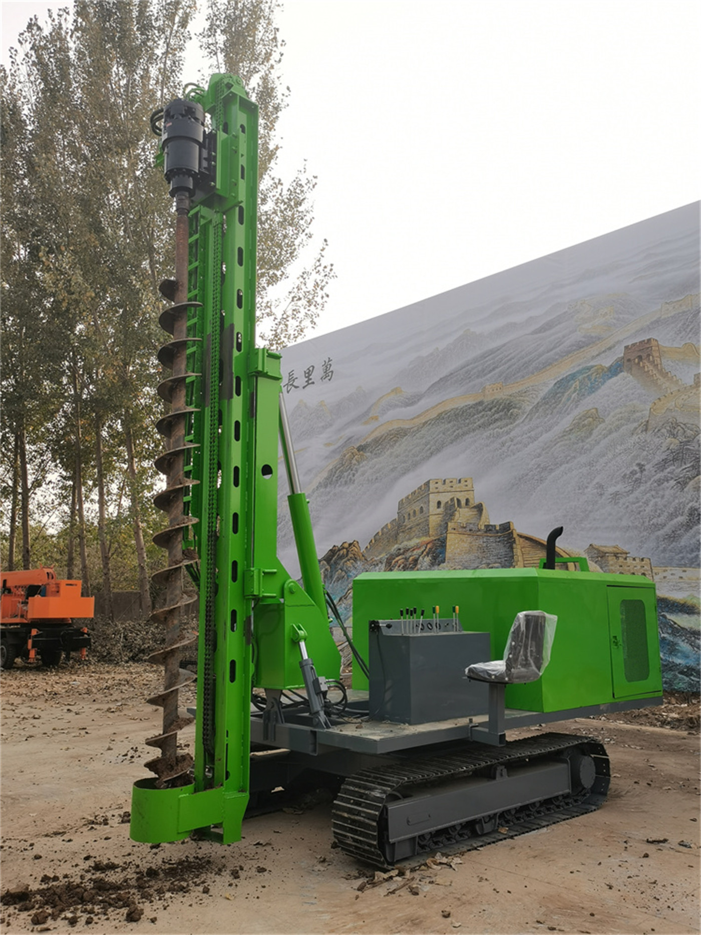
Step 3: Hole diameter and hole depth together map back to torque and drilling tools
Hole diameter and hole depth are not two independent conditions; together they determine the load during drilling, and this load corresponds to torque, rotation speed, and feed method. At this level, the PV390 publishes three items: 13,000 N·m reducer torque, 90 r/min drill rod rotation speed, and chain feed.
The materials describe torque as follows: it can cover the 80–600 mm drilling range; for large hole diameters, dense soil layers, and formations containing crushed stone, higher torque helps maintain rotation, but actual penetration still depends on the drill bit type, formation structure, and feed control. This statement does not directly convert torque into penetration rate, nor does it promise a drilling speed at a certain hole diameter. The description of chain feed also carries limitations—when encountering cobblestone, backfill layers, or strongly weathered rock, feed should be controlled according to rotation load and drilling tool condition to avoid excessive downward pressure causing hole deviation, sticking, or excessive impact on the drilling tools.
Therefore, the judgment that can be drawn at this step is directional: the larger the hole diameter and the denser the formation, the more critical torque and feed control become; however, the question of whether “13,000 N·m can drill in that project” cannot be answered by the materials themselves and requires separate confirmation in combination with the drill bit form and formation structure.
Step 4: Attitude conditions determine whether all pile positions can be completed continuously
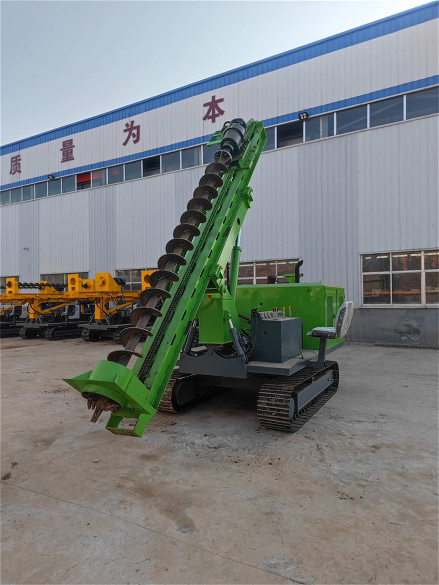
After decomposing the pile type, it is still necessary to return to the site to see how each pile position is aligned. This level corresponds to several attitude adjustment capabilities published for the PV390, and their roles do not overlap:
| Published item | Value | Corresponding action |
|---|---|---|
| Mast pitch | 120° | Adjust drilling attitude according to slope and pile position requirements |
| Mast swing | Dual-cylinder left-right swing arm | Perform lateral hole alignment after the machine is stabilized |
| Front-rear telescopic compensation | 50 cm | Longitudinal fine adjustment of pile position |
The materials describe these three capabilities together, with the effect of reducing full-machine fine adjustment at each pile position and improving the continuous construction rhythm for large-area array photovoltaic sites. The relationship of this level to pile type is that the higher the pile position arrangement density and the more uneven the ground, the more hole-alignment actions attitude adjustment must handle; when pile positions are sparse and the site is level, the value of this capability decreases relatively. The materials do not state how much machine repositioning each adjustment can reduce, so no quantitative inference is made.
Step 5: From pile position distribution back to chassis and passability
Only after pile type, hole diameter, hole depth, and attitude are confirmed should the final consideration be whether the equipment can complete these pile positions as required.
Relevant parameters published for the PV390 include: crawler chassis, 400 mm track shoe, 35° gradeability, overall dimensions 5200 × 2300 × 2650 mm, and an 85 kW Yuchai four-cylinder engine. The materials describe the track shoe as helping to distribute ground pressure, suitable for dirt roads, grassland, gravel ground, and slopes; for climbing, they clearly note that actual slope construction should still comprehensively consider cross slope, ground wetness, soil quality, and overall machine center of gravity, and that the maximum gradeability angle should not be used alone as the basis for safe travel.
The connection between this level and the previous steps is that the distribution pattern of pile positions determines how frequently the equipment needs to move, and the frequency of movement in turn affects the value of the chassis form. The materials' statements in this regard are limited to the above scope and do not address the passability conclusion for a specific site area.
Formation conditions are not part of the pile-type reverse-derivation chain, but they rewrite several of its steps
The PV390 materials provide corresponding descriptions by geological type; this part does not come from pile type, but is another parallel input:
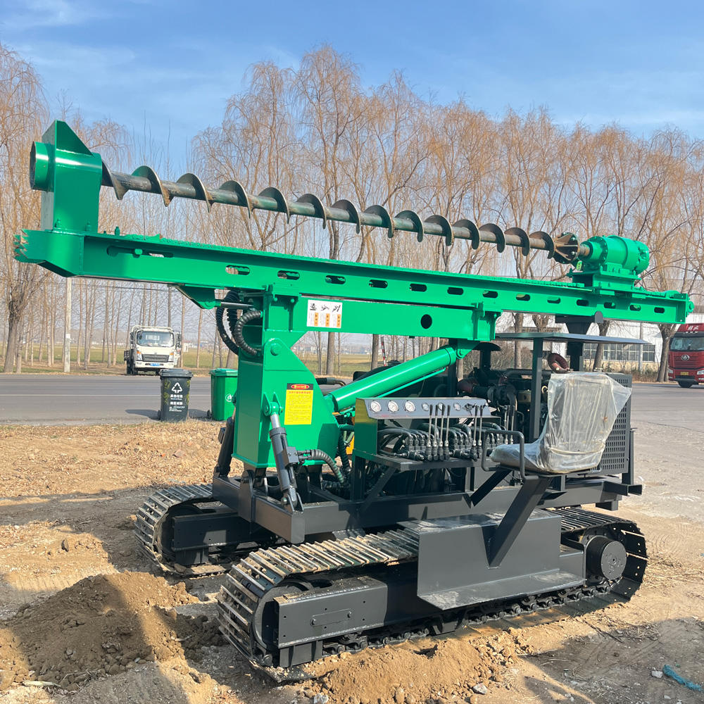
- Soil layer, loess: conventional pre-drilling; loess requires parameter adjustment according to density and moisture content
- Clay: pay attention to bit balling and poor cuttings removal
- Cobblestone sand: select drilling tools according to particle size and density
- Backfill waste layer: focus on preventing foreign objects, voids, and local jamming
- Strongly weathered rock and rock layers: the materials clearly state that after replacing with impact drilling tools it can be used for construction in corresponding formations, but do not give the impact hammer model or impact energy, so no additional explanation is made regarding hard rock efficiency
Once formation is included, the judgments from Steps 2 to 4 above will change: for the same pile type, the requirements for drilling tools and feed control are higher in backfill layers or gravel-containing formations. Formation data is a project-side input and must be provided by the project owner or obtained through separate investigation; it cannot be derived from equipment parameters.
What the materials cannot answer in this reverse-derivation chain
Following the above order, what can be determined within the scope of the materials is: whether the hole diameter falls within 80–600 mm, whether the hole depth falls within 0–6 m, whether the torque and feed method correspond to the described formation type, whether attitude adjustment can cover the on-site slope and pile position layout, and whether the chassis parameters and site passability conditions are at the same order of magnitude.
At least the following are not covered by the materials and need to be confirmed at the project level: the design hole diameter and hole depth corresponding to the specific pile type, the locations of underground cables, pipelines, and obstacles, the calculation of track adhesion and overall machine stability for slope operations, and the hole-forming quality and final drilling efficiency under the combined effect of pile type, hole diameter, construction angle, and operation method. The materials themselves state on this point: the final effect should be subject to on-site working conditions and the project foundation design.
In addition, the model in the original product materials is SL390, while the user's latest confirmed model is PV390; this article uniformly uses PV390. The remaining technical parameters are organized according to the provided materials.