












In the public documentation for the WRT1200, values are dense: 1200 m maximum drilling depth, 105–900 mm hole diameter, 61 T pull-up force, 13 T axial pressure, 24000/12000 N·m dual-condition torque, 75/150 r/min dual speed, 7/13 m feed stroke, 127 mm drill pipe, 1.65–8 MPa air pressure, 16–120 m³/min air consumption, 4 T + 3 T dual auxiliary winches, 220/264 kW diesel power, and 32 T overall weight. These numbers are placed close together in layout, but their meanings are distributed across different levels. Reading them as a parallel specification list easily gives the impression that “the larger the parameter, the more versatile”; reading them by reference relationships reveals that several sets of values actually constrain one another.
The following addresses only one question: among these values, which have clearly directed reference relationships, and which are merely placed side by side on the same page.
Drilling depth and hole diameter are not two independent upper limits
The documentation states drilling depth and hole diameter as follows: maximum drilling depth 1200 m, borehole diameter 105–900 mm. These two are often treated as two indicators that can simultaneously reach their limits, but the same passage immediately notes that a larger hole diameter facilitates configuring a larger well casing and submersible pump, while increasing drilling tool load, casing weight, cuttings removal demand, and air compressor load, and requires designing a reasonable hole diameter based on water yield, well casing, and pump type.
In other words, 105–900 mm is the executable hole diameter range of the equipment, and 1200 m is the depth range it can cover, but the two do not promise to be at their respective endpoints simultaneously in the same well. Once the hole diameter increases, the several sets of values on the load side (pull-up force, torque, air pressure, air consumption) must all be rechecked. The documentation gives this direction but does not provide paired values for how deep each hole diameter corresponds to—this needs to be confirmed separately according to the specific wellbore structure.
The 61 T pull-up force corresponds to the upward section in the hole
The documentation lists 61 T next to the pull-up force item and also gives 13 T axial pressure. These two numbers each govern a section and should not be interchanged: axial pressure governs the downward pressurization of the power head, and pull-up force governs the upward lifting stroke. The documentation lists the corresponding objects of pull-up force as deep-hole tripping, DTH hammer recovery, and some casing operations, and points out that as hole depth increases, drill pipe self-weight, casing weight, and borehole wall friction rise significantly.
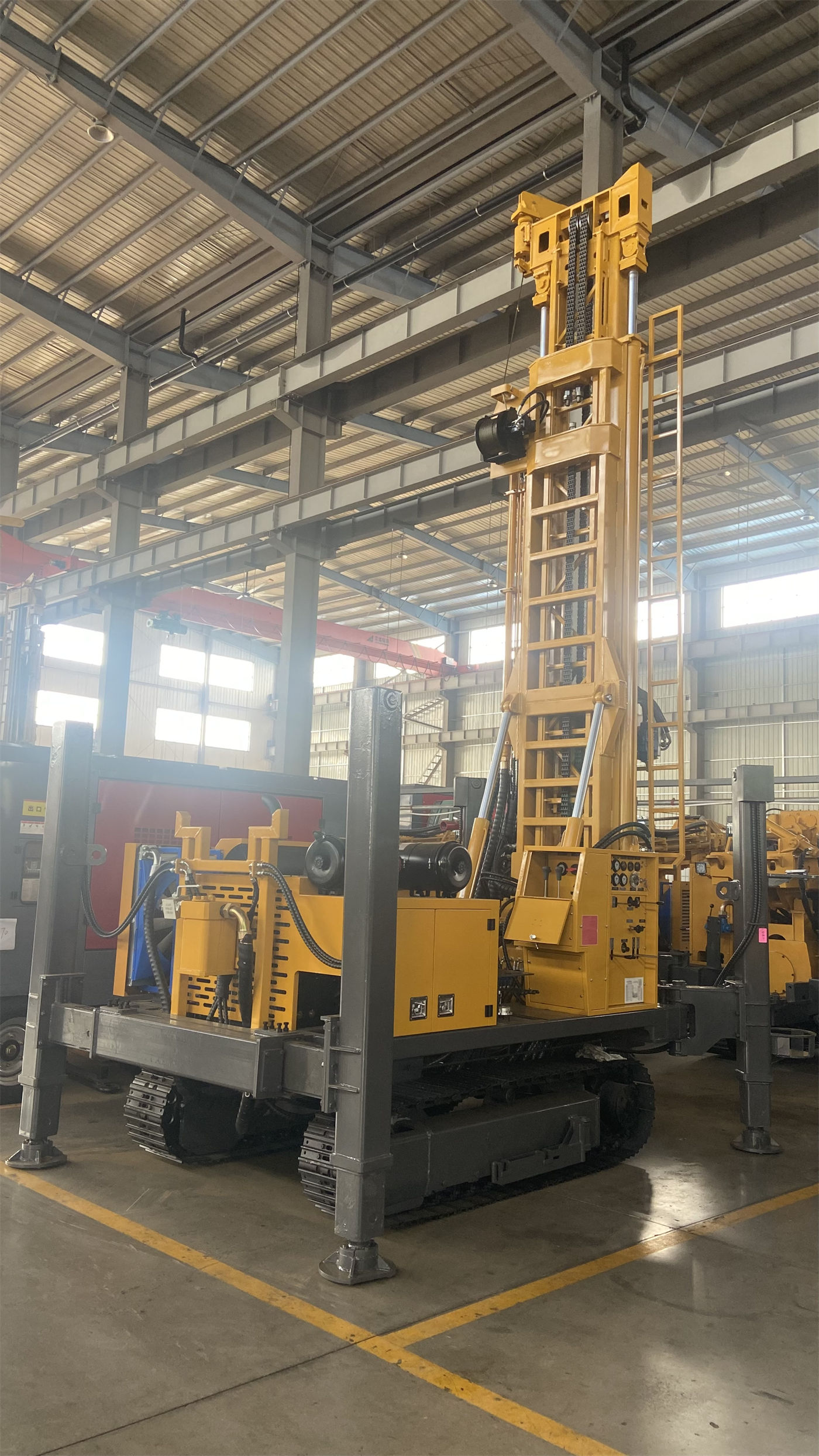
The same passage also has a constraint: if the tripping resistance is abnormal, the hole should first be cleaned and the condition of the borehole wall, drilling tools, and sediment judged; one should not simply rely on maximum pull-up force to pull forcefully. This sentence rewrites 61 T from “how much it can pull” to “under what conditions this margin is used,” and should not be skipped when reading the documentation.
24000/12000 N·m and 75/150 r/min are a set of values written and used together
The torque column states 24000/12000 N·m, and the rotation speed column states 75/150 r/min. The documentation states the correspondence between these two sets of values fairly directly: low speed and high torque are more suitable for large hole diameters, hard rock, and high-friction hole sections; the high-speed gear is suitable for stable formations with less resistance; and it prompts timely switching of operating conditions according to drilling tool load, cuttings return, and torque changes.
It should be noted that this set of dual-condition values and the pull-up force and axial pressure are not information at the same level. Pull-up force constrains the load of the drill string in the vertical direction, while torque constrains the rotary end; both act simultaneously in deep holes, but the documentation does not give a binding relationship that “a certain torque gear must be paired with a certain pull-up force gear,” and this should not be applied on one’s own.
Air pressure 1.65–8 MPa and air consumption 16–120 m³/min must be read together
In the DTH hammer section, the documentation gives recommended working air pressure of 1.65–8 MPa and air consumption of 16–120 m³/min. The same section also gives a judgment: if only pressure is met but displacement is insufficient, it may still lead to insufficient impact, difficult cuttings removal, and bottom-hole cuttings accumulation.
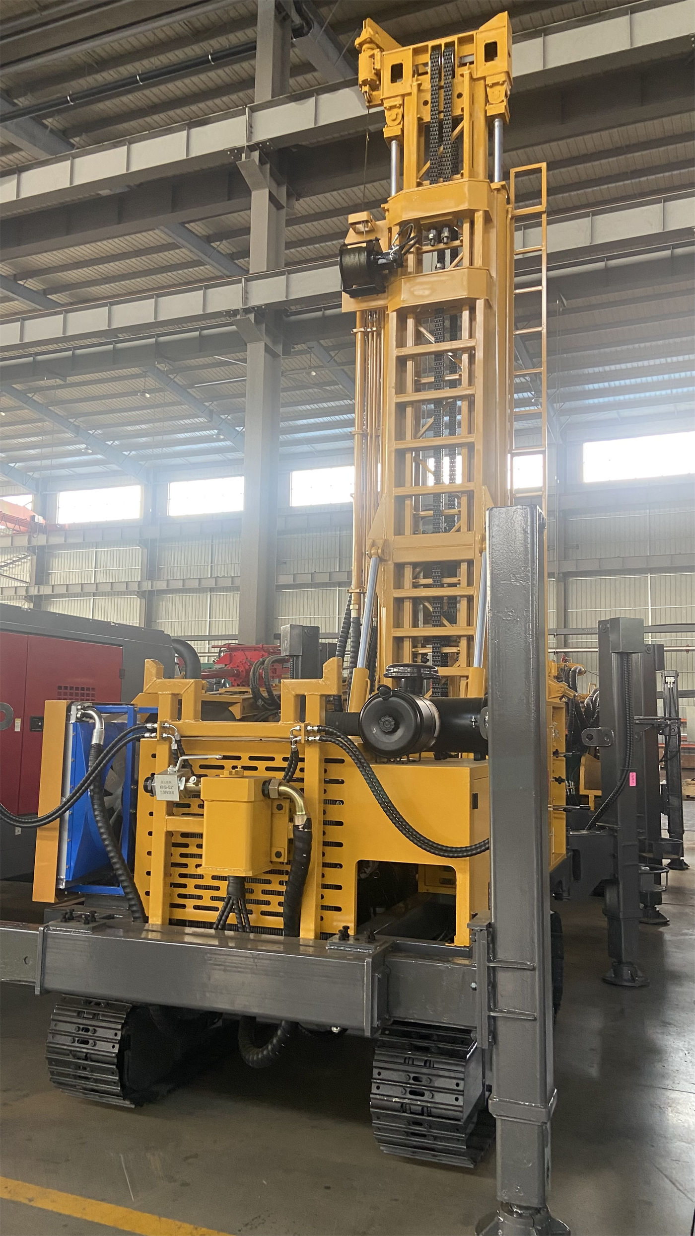
This sentence determines how these two numbers should be read: the air pressure range and the air consumption range must be satisfied simultaneously as one set of conditions, and the air compressor cannot be configured only according to the upper pressure limit. The documentation further explains that 1200-meter-class deep holes, large hole diameters, and hard rock conditions place very high demands on air compressor pressure and displacement. As for how much displacement a specific well requires, the documentation does not give a conversion basis, and this needs to be confirmed separately according to hole diameter, hole depth, and DTH hammer model.
7/13 m feed stroke and 3 m / 6 m drill pipe: two sets of values fall on the process rhythm
The documentation gives a feed/advance stroke of 7/13 m and explains that a longer stroke can reduce power head return and drill pipe operation frequency, making it more suitable for deep-hole projects pursuing continuous drilling efficiency, while the 7 m configuration more easily balances overall machine structure and site adaptability. In the drill pipe item, the same documentation states a recommended diameter of 127 mm, with drill pipe lengths supporting 3 m or 6 m; 6 m can reduce the number of pipe connections, while 3 m is more flexible in transportation, manual coordination, and restricted sites.
These two sets of values converge on the same process—pipe connection and return frequency. However, the documentation does not give a fixed combination of “which stroke pairs with which drill pipe,” nor does it give quantifiable time-saving data, so 13 m and 6 m should not be directly written as an efficiency account.
The relationship between 220/264 kW power and the remaining values is only touched upon in the documentation
The power column states two optional configurations, 220/264 kW. The documentation explains that selection can be based on the main hole diameter, rock formation hardness, auxiliary systems, and project load, and notes that long-term large-diameter or high-load hard rock construction should fully consider power reserve and heat dissipation capacity.
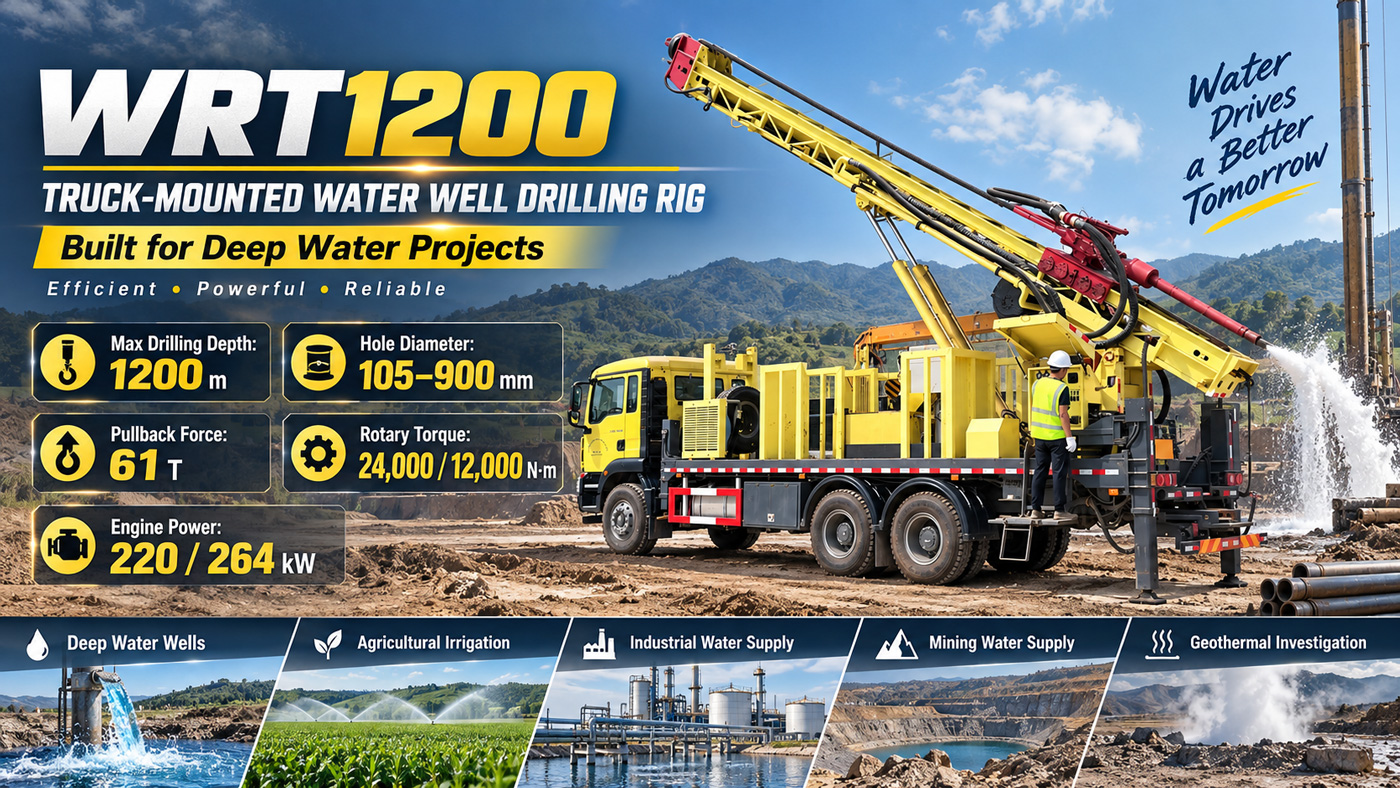
What can be obtained here is only direction: hole diameter, rock formation, and auxiliary systems will in turn affect power selection. The documentation does not provide a correspondence table of “a certain hole diameter range corresponds to a certain power configuration,” so the relationship between power and hole diameter is a part that needs to be confirmed with the supplier.
32 T overall machine and 11.5 × 2.25 × 3.2 m dimensions: constraining the transport profile of the straight mast structure
In addition to the overall weight of about 32 T and transport dimensions of about 11.5 × 2.25 × 3.2 m, the documentation also includes a statement about the straight mast structure: the straight mast has a more direct overall force path, making it suitable for long-term high-torque rotation, heavy drill string tripping, and casing operations, at the cost of a more fixed transport profile; before construction, road height limits, entry space, and site clearance should be confirmed.
This description links the two sets of values—structure and transport: the straight mast is not merely a choice of mast shape; together with the overall machine dimensions, it constitutes a condition that must be verified before entry. The verification items listed in the documentation include road width, bridge load-bearing capacity, turning radius, site bearing capacity, and overhead obstacles.
Which reference relationships the documentation has clarified, and which remain outside
- Clarified: the matching direction of dual-condition torque and dual-speed rotation; air pressure and air consumption must be satisfied simultaneously; the process links affected by feed stroke and drill pipe length; the relationship between the straight mast structure and transport profile.
- Direction only, with no correspondence table: the combined upper limits of hole diameter and drilling depth in the same well; the correspondence between hole diameter and power configuration; the specific air compressor displacement required under a certain hole diameter.
- Explicitly required by the documentation to be handled by special design: casing grade, cementing requirements, and circulation medium for geothermal development wells; special hydrological design for mine dewatering holes; filter pipes, water-stop sections, and pump type design during the well completion stage.
In addition, the daily inspection items for construction and relocation in the documentation are only a general description, and this article does not expand them into operating steps. All of the above is subject to the supplier’s technical confirmation documentation, and this article does not infer conversion bases not given in the documentation.