












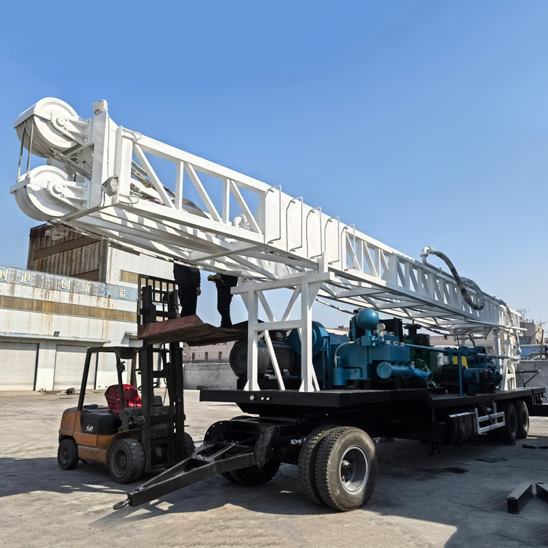
In the WRTR600 documentation, the equipment type is listed as a "trailer-mounted rotary table drilling rig," alongside an SCGC-200kW diesel generator set and a 3NB-130 mud pump. These three items are not three separate pieces of equipment assembled for a project; they are arranged together on the same trailer chassis. Viewing the generator and mud pump as separately purchased components to be positioned on site versus viewing them as part of the chassis that arrives as a unit corresponds to two different approaches to site organization.
What Is Mounted on the Same Chassis
According to the documentation, the components arranged on the trailer chassis include: diesel generator, 3NB-130 mud pump, rotary table, double winch, mast, outriggers, and auxiliary breakout mechanism. The trailer-mounted installation format means the entire drilling rig can be transferred between projects using a suitable towing vehicle.
One point deserves separate attention: the documentation does not describe the generator set and mud pump as "optional" or "separately orderable," but lists them alongside the rotary table and winch in the same arrangement description. In other words, within the framework of this documentation, the power source and circulation system are part of the complete machine, not add-ons to be supplemented after arrival on site.
What the 200 kW Generator Does in the Integrated Layout
The SCGC-200kW diesel generator set specifications are: rated power 200 kW, rated voltage 380 V, rated current 360 A, frequency 50 Hz. The stated purpose is to supply power to the mud pump, hydraulic oil pump, and auxiliary electrical equipment, suitable for remote areas and projects lacking a stable power grid.
Reading these items together, the power supply targets are clear: the mud pump is one electrical load, and the hydraulic oil pump is another. The 3NB-130 mud pump is driven by a 90 kW motor, and the hydraulic gear oil pump CB-E532F is driven by an 11 kW motor. Both fall within the 200 kW supply range, but the documentation does not provide load calculations for simultaneous operation, nor does it list the power details of the remaining auxiliary electrical equipment.
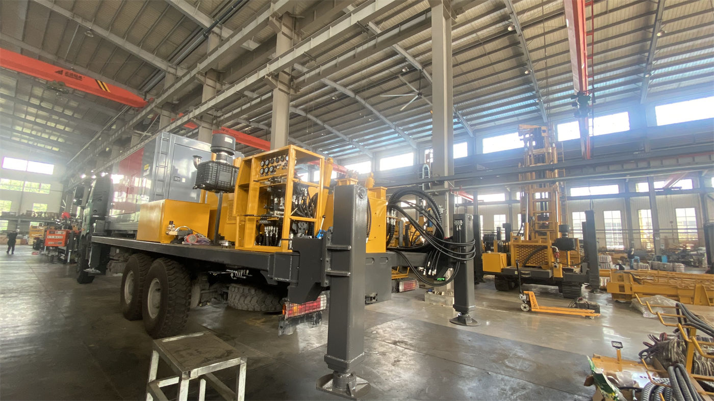
Therefore, the significance of this generator is not that "no external power is needed on site," but that it provides a power source that arrives with the chassis for projects without a stable grid. Whether it can cover the entire power demand of a specific job site cannot be answered from the documentation and requires separate calculation based on actual site loads.
Where the 3NB-130 Circulation Parameters Fall
The 3NB-130 mud pump has a specified displacement of 8.4–16.6 L/s, rated working pressure of 5–10 MPa, input speed of 565 r/min, and drive power of a 90 kW motor. The documentation describes its function as: carrying drill cuttings, cooling the drill bit, maintaining borehole wall stability, and controlling downhole pressure, and calls it an important system for construction in loose formations.
The coexistence of displacement and pressure ranges on the same pump indicates an adjustable range rather than a fixed output point. The documentation's approach to mud properties is also noteworthy: in soil, clay, and soft overburden, mud viscosity should be adjusted according to formation permeability, hole diameter, and return conditions; too thin may result in insufficient cuttings removal and borehole wall instability, while too thick increases circulation resistance and mud pump load. In sand, gravel, and loose overburden, appropriate mud properties can be used in combination with temporary casing or staged casing.
In other words, the pump's displacement range provides adjustment space, but the specific value still depends on formation, hole diameter, and return conditions—all of which are mentioned in the documentation, but the specific mud mix ratios and displacement settings for each are not provided.
After Integration, What Changes During Relocation Is Not Drilling Depth
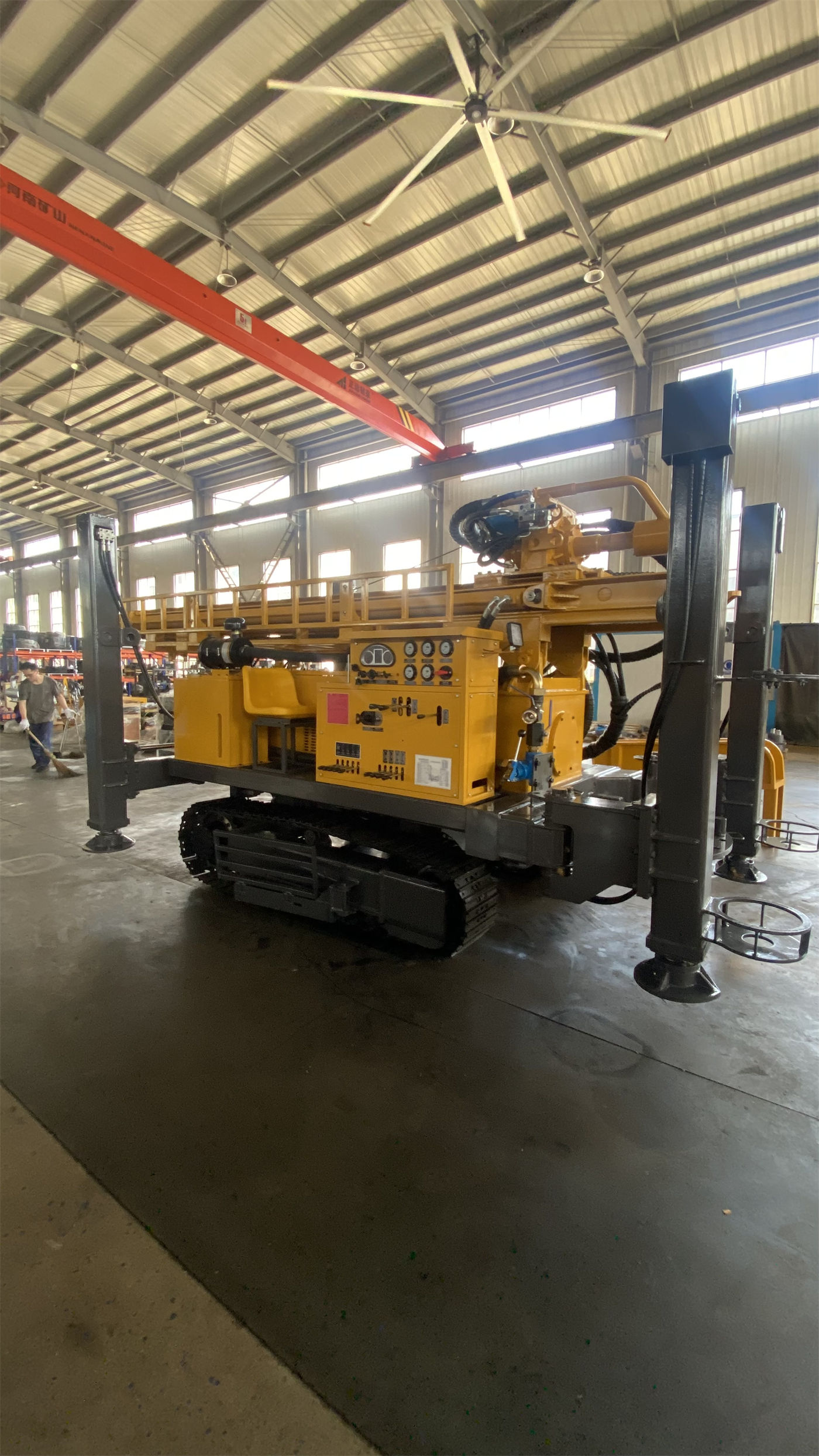
Drilling depth and hole diameter parameters do not change due to integration. What integration truly affects is transport and site layout.
| Item | Short Mast Version | Long Mast Version |
|---|---|---|
| Transport dimensions | Approx. 15100 × 2480 × 4100 mm | Approx. 16630 × 2480 × 4100 mm |
| Working dimensions | 15100 × 2480 × 14170 mm | 15100 × 2480 × 17170 mm |
| Effective mast height | 12 m | 15 m |
| Kelly | 108 × 108 × 7500 mm | 108 × 108 × 10500 mm |
| Drill pipe | Ø89 × 10 × 5500 mm | Ø89 × 10 × 9000 mm |
The two transport dimension sets have the same width and height, with the difference mainly in length. The documentation's reminder for trailer transport is: before cross-regional construction, confirm road width, turning radius, bridge load capacity, height restrictions, and local trailer transport requirements. These conditions apply to the entire machine as a single transport unit, not to dispersed components—this is precisely the direct constraint that the integrated structure brings during relocation.
Short and Long Masts Change the Rod Connection Process
The documentation states the division of labor between the two mast types plainly: the short mast version is equipped with a 7.5 m kelly and 5.5 m drill pipe, while the long mast version is equipped with a 10.5 m kelly and 9 m drill pipe; the short mast is more conducive to transport and site adaptability, while the long mast reduces the number of rod connections and improves continuous drilling efficiency for deep holes.
This difference does not involve the maximum drilling depth, but rather the auxiliary time outside each round trip. The long mast reduces the number of rod connections, while the short mast provides shorter transport length and better site adaptability. The trade-offs differ, and the documentation does not conclude which is superior.
Downhole Loads Are Still Borne by the Rotary Table, Winch, and Swivel
Integration does not change the values at the downhole end: rotary table three-speed 38 / 57 / 85 r/min, corresponding theoretical torque approximately 13.8 / 9.2 / 6.2 kN·m; main winch single-line pull 40 kN, auxiliary winch single-line pull 30 kN; swivel maximum load 30 T, inner diameter 63.5 mm. The documentation explains that as hole depth increases, drill string weight and borehole wall friction gradually rise, so matching between the swivel, winch, kelly, and drill pipe is important.
Lower speed gears provide higher torque, suitable for larger hole diameters, heavy drilling tools, and formations with greater resistance; higher speeds are suitable for drilling stages with less resistance. These judgments are based on the same set of values and are independent of whether integration is used.
Several Conditions the Integrated Structure Imposes on Site Preparation
The inspection items listed in the construction precautions are themselves a reflection of the integration scope: mast, winch, wire rope, swivel, rotary table, mud pump, generator, and electrical system. It should be noted that this documentation lists inspection items but does not provide specific inspection steps, intervals, or acceptance criteria for each; these need to be separately confirmed by the user according to their own procedures.
Two other site conditions explicitly stated in the documentation: when raising the mast, confirm there are no overhead lines or obstacles above; during mud circulation, pay attention to high-pressure lines, pump pressure, and leaks. Personnel must not stand under suspended drilling tools or near rotating drilling tools.
What the Documentation Does Not Answer
The following items have no corresponding data in the WRTR600 documentation on this site and cannot be concluded from the available text:
- The actual load margin of the 200 kW generator when the mud pump, hydraulic oil pump, and auxiliary electrical equipment operate simultaneously;
- The specific displacement settings and mud mix ratios for the 3NB-130 under different formations and hole diameters;
- The towing vehicle specifications and towing parameters required for trailer transport;
- The overall machine weight, axle load distribution, and regulatory requirements for trailer units in various locations;
- The daily maintenance intervals and consumable parts lists for integrated components such as the generator and mud pump.
The documentation's statement on drilling performance is: due to differences in actual geological conditions, downhole tools, drilling angle, and operating methods, the final drilling efficiency, drilling depth, and well completion results should be based on actual site conditions. This limitation also applies to the performance of the integrated configuration in actual projects.