












The public information for the WR260 defines the boundaries of a single machine: maximum drilling depth of 260 m, borehole diameter of 140–305 mm, rotary torque of 4000–5300 N·m, lifting force of 15 T, 76 kW diesel power, and for DTH hammer drilling, reference working air pressure of 1.7–2.5 MPa and air consumption of 17–31 m³/min. These values belong to the equipment side. What pre-entry preparation must do is fill in the conditions on the project side: where the well site is, what diameter to drill, what rock formations lie below, whether the air compressor displacement is sufficient, and which type of drill pipes and hole stabilization materials to prepare. A common cost of reversing the order is discovering that the well diameter has changed after materials arrive, or that the air compressor displacement does not match the selected DTH hammer. The following is arranged in an executable sequence, based only on information already published on this site.
1. Well Site and Diameter: First Define Conditions, Then Equipment Parameters
In the information, the WR260's borehole diameter is stated as 140–305 mm. The two ends of this range correspond to different well casings and submersible pump configurations. The information explicitly requires: before well completion, the well depth, well diameter, filter pipe, and sealing intervals should be determined based on the aquifer position, expected water yield, and local water quality requirements. In other words, the well diameter is not chosen first; it is derived from the purpose of the well.
Even for water wells, the information divides usage scenarios into several categories with different conditions:
- Rural domestic water and community water wells: the well casing and submersible pump configuration determine the well diameter range.
- Farmland irrigation and orchard water supply: well diameter is related to the water yield target, and the crawler chassis also involves whether it can move smoothly between hole positions.
- Livestock farm and pastoral area water supply: long-term stable water extraction is required, and the well site should still be selected based on local hydrogeological conditions.
- Mining areas, exploration camps, and construction projects: if the proportion of hard rock is high, the information suggests focusing on matching the DTH hammer and air compressor.
- Factory and engineering construction water: the equipment dimensions are approximately 3900 × 1750 × 2250 mm, and entry conditions for factory areas and space-restricted areas must be checked in advance.
At this step, three things must be finalized: well site coordinates, well completion structure (well diameter, well casing, filter pipe, sealing intervals), and expected final hole depth. The final hole depth does not necessarily have to be drilled to the full 260 m; in the information, 260 m is the equipment's maximum drilling depth, not the target well depth for every project.
2. In-Hole Process: Correspondence Between Hole Stabilization Method and Air Compressor
The WR260's main drilling method is stated as DTH hammer drilling, but the information gives different prerequisites for different formations, and they cannot all be handled with the same process.
| Formation/Working Condition | Handling Direction Given in the Information |
|---|---|
| Relatively intact rock formations such as limestone, sandstone, and granite | Use after matching with a suitable DTH hammer, drill bit, and air compressor |
| Weathered rock and alternating soft-hard formations | Adjust feed and rotation in a timely manner; use casing to protect unstable upper hole sections when necessary |
| Soil layers, clay, sand layers, and gravel overburden | Not suitable for direct DTH hammer use; select casing, mud, or other hole stabilization methods according to the formation |
| Fracture zones and formations with developed fissures | Reduce excessive feed rate and maintain cuttings removal and hole cleaning; for thicker fracture zones, consider casing or foam assistance |
| Karst caves, open fissures, and formations with severe air leakage | May require foam, casing, increased air volume, or a change in construction method |
For the air compressor, two values must be matched: reference working air pressure of 1.7–2.5 MPa and air consumption of 17–31 m³/min. The information also notes that when borehole diameter increases, rock formations become harder, or altitude rises, a more sufficient air flow rate is usually required. Insufficient displacement will directly manifest as insufficient DTH hammer impact and difficult cuttings removal. The conclusion at this step is: the air compressor specifications can only be determined after the well diameter and rock formations are defined, not the other way around.
After entering the aquifer, groundwater will change the DTH hammer operation and rock powder discharge status. The information requires adjusting air supply and hole cleaning methods according to the water inflow, and recording the depth of the main aquifer. This record will also be needed later for well completion piping.
3. Drilling Tools and Hole Stabilization Materials: Follow the Well Diameter and Process
The information states that the WR260 can be used with 76 mm or 89 mm drill pipes, with a single feed length of 3.3 m, and can match 1.5 m, 2 m, and 3 m drill pipes. These three sets of values determine the rod connection rhythm and material preparation quantity, rather than being optional free choices.
The preparation of hole stabilization materials is based on the formation judgment from step 2:
- When casing, mud, or other hole stabilization methods are needed for overburden sections, the specifications and quantity of casing should be prepared according to the length of the upper hole section.
- When the fracture zone is thick and foam assistance is needed, materials should be prepared and delivered to the site in advance.
- Karst caves and formations with severe air leakage may require increased air volume or a change in construction method. Such judgments should be formed into a plan before drilling starts, rather than being decided on an ad hoc basis after air leakage occurs in the hole.
For the well completion stage, the information only states "reasonably configure well casing, filter pipe, and water-stop structure according to the aquifer position," without giving specific specifications and dimensions. This part needs to be determined separately in conjunction with local hydrogeological data.
4. Site and Power: Crawler Chassis Is Not a Passage Permit
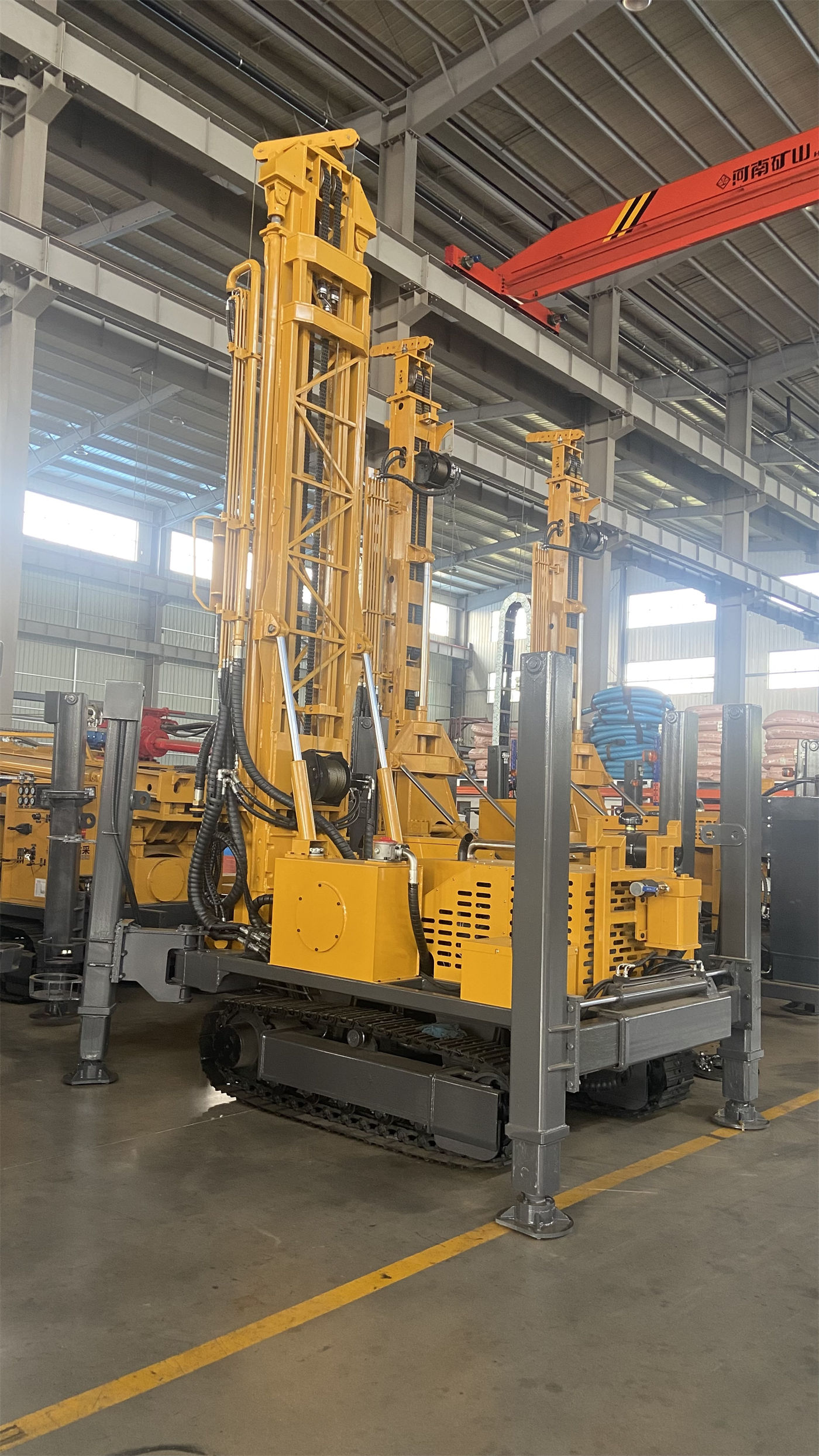
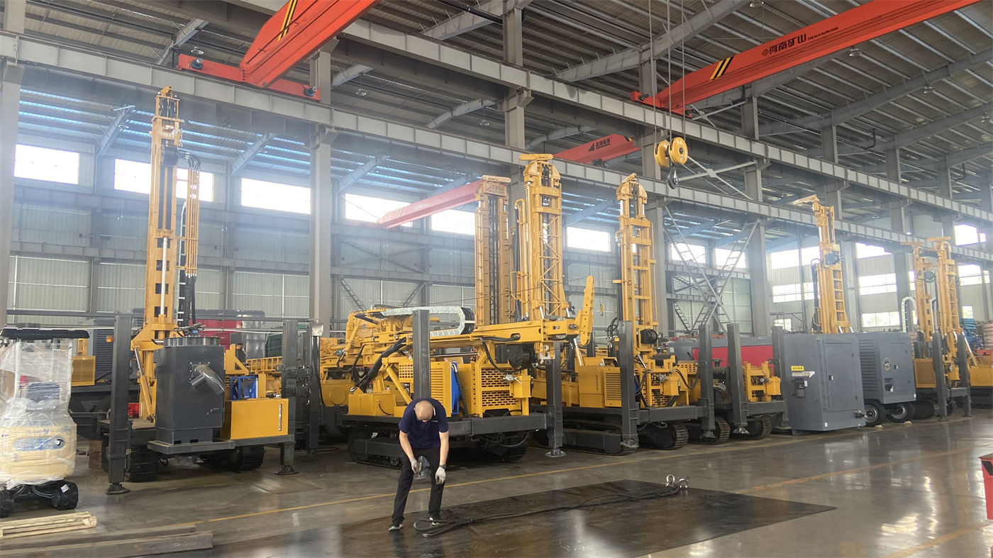
The WR260 uses a steel crawler chassis, with a travel speed of approximately 2.5 km/h, a reference maximum gradeability of 30°, and an overall weight of 5.7 T. The crawler chassis is suitable for gravel ground, rural roads, and mining sites, but the information gives a clear prerequisite for relocation: when relocating the equipment, the mast should be retracted and the slope and ground bearing conditions should be evaluated.
The high outrigger stroke is 1.4 m, which can support and level the machine on mildly uneven ground. The information also requires ensuring the stability of the entire machine before drilling. On soft ground, additional pads are needed to prevent outrigger settlement from causing mast tilt and hole position deviation. Pads are part of the entry materials and should be included after site conditions are confirmed.
In terms of power, the information gives a 76 kW diesel engine, with an optional electric motor power solution suitable for factory areas, mines, or fixed construction projects with stable power supply conditions. The information notes that the final motor power, voltage, and control method should be based on the formal configuration—that is, when choosing the electric drive route, the power supply capacity and control method are matters that need to be confirmed with the manufacturer and cannot be inferred from diesel engine parameters.
A 1.5 T auxiliary winch is configured with the equipment for handling DTH hammers, drill pipes, casing tools, and some on-site auxiliary equipment. The information reminds that lifting loads should be controlled and personnel should be kept away from suspended objects.
5. Pre-Drilling Inspection and Parts Requiring Separate Confirmation
The daily inspection items listed in the information cover: engine, hydraulic system, rotary head, mast, winch, and high-pressure air hose; during operation, continuously observe air pressure, cuttings removal, water return, and equipment temperature; after completion, clean mud and dust, and check drill pipe threads, DTH hammer lubrication, and hydraulic connectors. When relocating frequently, also check the crawler and loading fixation points.
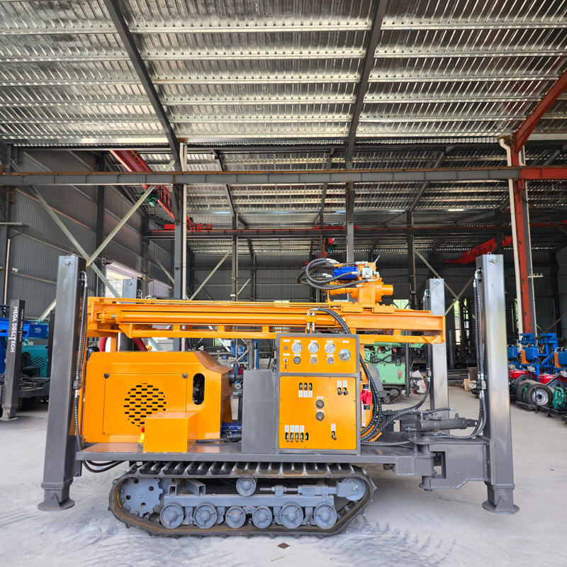
Applying these to the entry milestone means a pre-drilling item-by-item inspection: drill pipe threads and DTH hammer lubrication are confirmations on the consumables side, hydraulic connectors and high-pressure air hoses are confirmations of connections, and the mast and outriggers are confirmations of overall machine stability.
There are two places where the information itself indicates the need for separate confirmation:
- In the WR260 information, one parameter of 2.73 m is labeled "Width of loading," which is inconsistent with the overall external width of 1750 mm. This article retains it as labeled in the information and does not interpret it as the actual transport width; the final value should be confirmed with formal production technical data.
- The motor power, voltage, and control method of the optional electric power are likewise subject to the formal configuration.
The information also gives a reference drilling efficiency value of 10–35 m/h, as well as fast lifting of 24 m/min and fast feed of 40 m/min. It should be clarified that the latter two values are used for drill pipe handling, power head return, and non-drilling stages, not the actual penetration rate in the formation. Actual drilling efficiency, drilling depth, and well completion results still depend on lithology, borehole diameter, DTH hammer, and air compressor performance, and should be based on on-site working conditions.
Summary of Preparation Sequence
Organizing the above content in order, before entry the following should be implemented sequentially: well site, well diameter, and well completion structure → formation of each hole section and corresponding hole stabilization method → air compressor pressure and displacement → drill pipe and hole stabilization material preparation → site access, outrigger pads, and power form → pre-drilling inspection of the entire machine and drilling tools. The input for each step comes from the previous step. Skipping any step will result in items that need to be revised later.