












The WR400S materials begin with one sentence: 400 m maximum drilling depth, 105–325 mm hole diameter, and direct operation with 6 m drill pipes and 6 m casing. These three conditions appear in the same sentence, indicating that they are not three independent selling points, but a set of premises that must hold simultaneously. Taking 400 m alone as a selection conclusion would miss the constraints imposed by hole diameter, drill string length, and downhole load. This article follows the reverse order of "target well depth—supporting conditions" and divides the published WR400S values into six groups for item-by-item verification, using only the product descriptions and parameters already available on this site, without making inferences beyond the materials.
Group 1: Hole diameter and well completion structure—first framing the applicable range of drilling depth
The WR400S drilling diameter is stated as 105–325 mm, with a maximum drilling depth of 400 m. These two values appear side by side in the same document, but the document does not state that 400 m can also be achieved at a 325 mm hole diameter. The larger the hole diameter, the larger the annular space in the hole, the higher the return cuttings air volume requirement, and the greater the rotational resistance of the drill string. This is common knowledge at the process level, but how many meters of drilling depth correspond to a specific hole diameter must be calculated in combination with actual formations. Therefore, what this group of conditions can confirm is the hole diameter range; what it cannot confirm is that the upper limit of the range and 400 m hold simultaneously.
The well completion structure must also be considered together: the arrangement of well casing, screen pipes, and sealing sections will change the final hole diameter and casing installation procedure. The materials mention that during the well completion stage, well casing, screen pipes, and sealing sections need to be reasonably arranged, but they do not provide specific completion plans for each diameter. This part should be designed separately in combination with local hydrogeological conditions.
Group 2: Lifting force and axial pressure—corresponding to two different strokes: pulling out and applying pressure
The WR400S lifting force is stated as 22 T, and axial pressure as 4 T. The materials clearly explain that these two values do not govern the same thing: lifting force corresponds to normal tripping, tool recovery, and the margin when pulling out is obstructed; axial pressure corresponds to the stroke where the power head presses downward. The materials also give one usage limitation: if abnormal pulling resistance occurs, the hole should first be cleaned and the presence of underreaming, falling blocks, or stuck drilling should be judged, and the maximum lifting force should not be used directly to force handling.
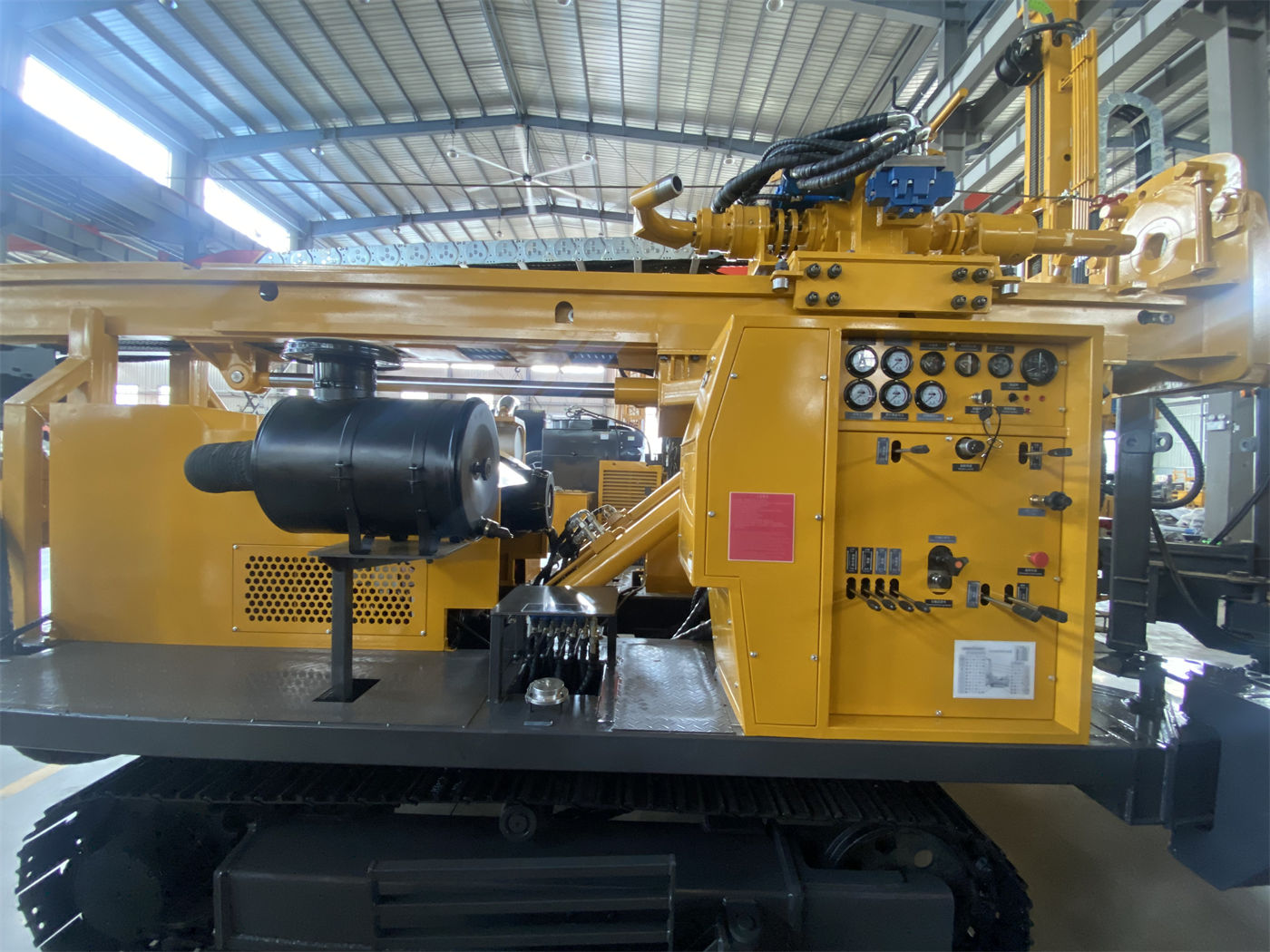
Reading this limitation together with 22 T means that 22 T is the upper capability limit at the equipment end, not a universal solution for any downhole situation. In 400 m-class boreholes, the self-weight of the drill pipe, borehole wall friction, and casing weight accumulate with depth. To judge whether 22 T is sufficient, the drill string assembly, hole diameter, and borehole wall condition must be calculated together. The materials do not provide drill string weight data for each hole diameter, so this item needs to be supplemented by the manufacturer.
Group 3: Torque and rotation speed—dual working conditions are not two speed gears
The WR400S rotary system is stated as maximum torque 8000 / 4000 N·m, corresponding to maximum rotation speeds of 75 / 150 r/min. These two sets of numbers are written and used together: the low-speed state has high torque and low rotation speed, corresponding to larger hole diameters and higher resistance; the high-speed state has low torque and high rotation speed, corresponding to drilling stages with lower resistance. The materials say "switch according to drill string, rock formation, and cuttings return conditions," and do not describe it as two fixed speed gears. Therefore, there is no fixed answer such as "which gear to use for hard rock."
What this group of values can support is the room for working condition switching; it cannot directly derive a recommended parameter combination for a specific formation, because besides rotation, the rate of penetration, air volume, and bit condition will also change the downhole load.
Group 4: Working air pressure and air consumption—the air compressor must be selected according to both items simultaneously
When using a DTH hammer, the recommended working air pressure for the WR400S is 1.2–3.5 MPa, and air consumption is 16–55 m³/min. The materials clearly point out that air compressor selection needs to consider both pressure and displacement simultaneously, and note that in large-diameter, hard rock, and high-altitude environments, insufficient displacement will directly affect impact and cuttings removal.
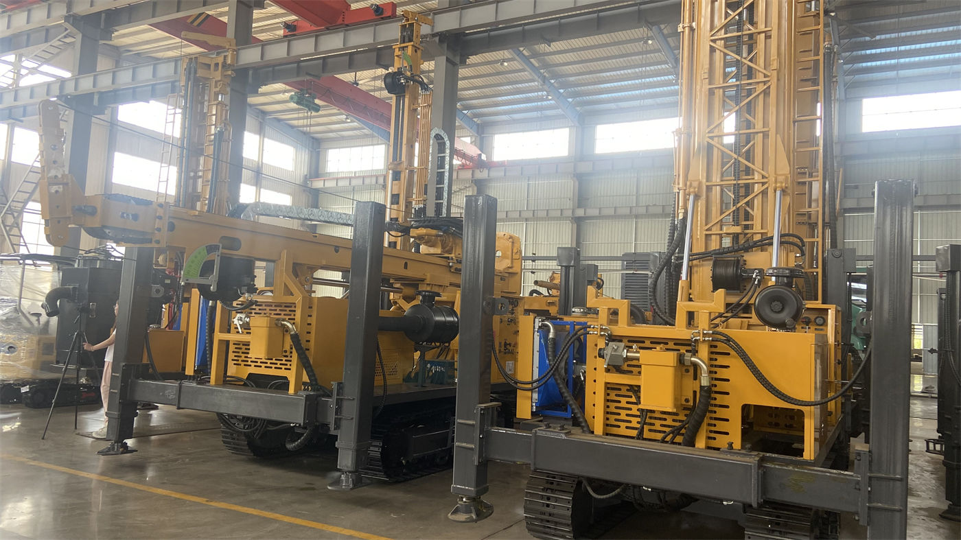
This group of conditions is the one most easily compressed when working backward from 400 m drilling depth: air pressure determines whether the DTH hammer can work normally, and displacement determines whether rock cuttings at the hole bottom can be continuously carried out. When the hole diameter reaches the 325 mm end and the hole depth approaches 400 m, the cuttings return path becomes longer, and air consumption toward the upper end of the range deserves more attention. The materials do not provide recommended displacement values for specific hole diameters and depths; the actual configuration should be verified with the manufacturer or air compressor supplier.
Group 5: Drill pipe and casing length—determining the number of connections and disconnections
The WR400S supports direct operation with 6 m drill pipes and 6 m casing, with recommended drill pipe diameters of 89 / 102 mm. The materials explain this point as follows: long drill pipes can significantly reduce the number of pipe connections in 300–400 m-class water wells, lower auxiliary time and manual handling frequency, and place this improvement at the level of "actual construction rhythm," rather than directly equating it with penetration rate.
Also appearing in this group are fast lifting at 29 m/min and fast advancing at 56 m/min. The materials explain that these two items are used for power head return, drill pipe handling, and non-drilling actions, while actual formation penetration still depends on rock hardness, hole diameter, bit, DTH hammer, and air compressor capability. The position of the telescopic mast in this chain is: in transport state it shortens the overall machine profile, and in working state it continues to support 6 m drill pipes or 6 m casing, mainly for construction organization requiring frequent loading and site transfer.
Group 6: Overall weight, dimensions, and chassis conditions
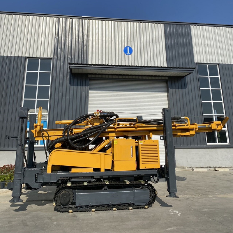
The WR400S overall weight is about 9.8 T, dimensions are about 6.26 × 1.85 × 2.43 m, walking speed is about 2.5 km/h, maximum climbing angle reference is 21°, hydraulic outrigger stroke is 1.6 m, auxiliary winch lifting force is 1.5 T, and power is a 92 kW Yuchai engine. The materials' explanation of these values focuses on the construction organization side: the crawler chassis is suitable for rural roads, gravel ground, and generally uneven sites; before site transfer, the mast should be placed in a safe transport state, and ground bearing capacity, slope, and wet slippery conditions should be assessed; on soft ground, pads should be used to ensure even force on the outriggers.
The materials do not provide road passage width, bridge load limits, or specific site bearing values. Such conditions need to be verified separately according to the project location, and "can enter the site" cannot be directly inferred from the overall dimensions.
Checklist placing the six condition groups together
| Supporting condition | WR400S published values | What can be confirmed when working backward | Parts not covered by the materials |
|---|---|---|---|
| Hole diameter and drilling depth | 105–325 mm, maximum 400 m | The hole diameter range and drilling depth upper limit each hold | Actual drillable depth corresponding to each hole diameter |
| Lifting and pressure application | 22 T / 4 T | Clear margin for tripping and recovery | Downhole load under different drill string assemblies |
| Rotation | 8000 / 4000 N·m, 75 / 150 r/min | Room for switching between two working conditions | Recommended parameter combinations for specific formations |
| Air supply | 1.2–3.5 MPa, 16–55 m³/min | Air pressure and displacement need to match simultaneously | Displacement values for specified hole diameters and depths |
| Drill string length | 6 m drill pipe, 6 m casing, recommended 89 / 102 mm | Reduces the number of pipe connections in 300–400 m-class wells | Applicable hole sections for different drill pipe diameters |
| Overall machine and site | About 9.8 T, 6.26 × 1.85 × 2.43 m, climbing reference 21° | Reference for transport profile and walking conditions | Road passage width and bearing conditions |
What this reverse-order approach cannot answer
The six condition groups can frame the capability items at the equipment end, but the final completed well depth is ultimately determined by hydrogeological conditions. The materials themselves also state that "the actual completed well depth should still be determined according to hydrogeological conditions," and recommend reasonably determining the target well depth in combination with local hydrological data before formal construction. In addition, mud pumps, centrifugal pumps, generators, and foam pumps are optional accessories. The selection principle given in the materials is to configure according to actual working conditions: loose layer projects need a mud system more, hard rock projects focus on configuring air compressors and DTH hammers, and formations with severe air leakage may use foam assistance. Which items to configure for a specific project and what specifications to use are matters that need separate confirmation with the manufacturer.