












The WR400QS data begins with several parallel values: 400 m maximum drilling depth, 105–325 mm drilling diameter, 6 m drill pipe, and 22 T lifting force. These four items are written in similar positions and are easily recorded as four independent capability indicators. However, based on the internal wording of the data, they are closer to appearing in pairs: drilling depth only holds within the aperture range, the value of the 6 m drill pipe lies in the number of pipe connections, and the 22 T lifting force corresponds to the load of the drill string and casing at 300–400 meter level hole depths. This article breaks down several groups of values according to their pairing relationships, using only the descriptions and parameters already published on this site for the WR400QS.
Group 1: 400 m Drilling Depth and 105–325 mm Aperture
The data states the maximum drilling depth as 400 m and the drilling diameter as 105–325 mm, and adds in the same paragraph: the final well depth should still be determined in conjunction with local hydrogeological conditions. The meaning of this sentence is that 400 m and 105–325 mm are not two upper limits that can each be taken to their extremes. When the aperture approaches the 325 mm side, the annular volume in the hole, the cuttings return requirements, and the drill string load will all change, and the actually achievable hole depth usually requires separate judgment. The data does not provide a corresponding drilling depth table for different apertures, so "400 m + 325 mm" cannot be treated as an already verified combination.
Group 2: 6 m Drill Pipe and 89 / 102 mm Recommended Diameter
The WR400QS directly supports 6 m drill pipe, with recommended drill pipe diameters of 89 / 102 mm. These two items should be read together: the drill pipe length determines the number of connections and disconnections, while the drill pipe diameter determines the self-weight and stiffness of the same drill string in the hole. The data's explanation of long drill pipe focuses on one point—reducing the frequency of pipe connections, which is especially noticeable in 300–400 meter level water well projects, with less auxiliary time. However, the data does not provide calculations of the number of pipe connections at different hole depths, nor does it constitute a judgment on penetration rate.
Group 3: 22 T Lifting Force and 4 T Axial Pressure
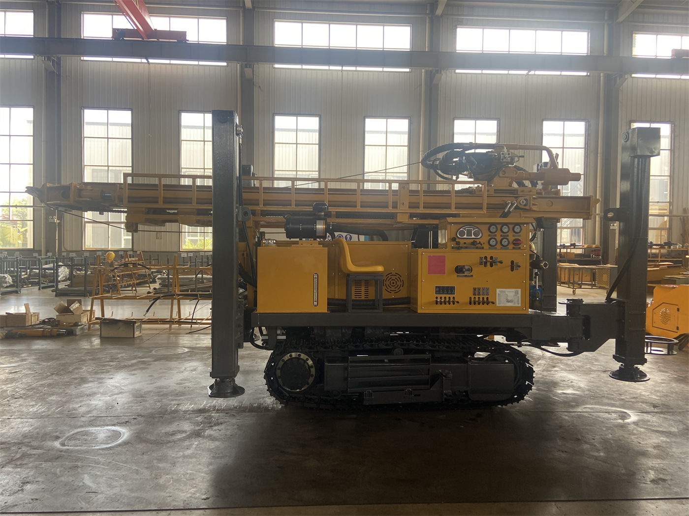
The 22 T lifting force and 4 T axial pressure belong to two directions in the same document. Axial pressure governs the section where the power head presses downward; lifting force governs the section where it pulls upward, including the entire drill string, tool recovery, and casing handling. When discussing the 22 T, the data adds a qualification: when encountering stuck drilling, hole shrinkage, or wall collapse, priority should still be given to resolving the issue through hole cleaning and process adjustment, rather than simply relying on maximum lifting force to pull forcefully. This qualification itself shows that 22 T is the upper limit on the equipment side, not a universal solution for all problems in the hole.
Group 4: 8000 / 4000 N·m and 75 / 150 r/min
The two sets of values for the rotary system are written as pairs: maximum torque 8000 / 4000 N·m, corresponding to maximum rotation speeds of 75 / 150 r/min. The data explains that low speed and high torque are more suitable for large aperture, hard rock, and high-load conditions, while higher rotation speeds are suitable for stages with relatively lower resistance, and suggests that the site should select the working condition according to aperture, drilling tools, and rock formation changes, avoiding long-term fixed use of a single rotation speed. The reason this is easily read as "two speed gears" is that the dual working conditions do indeed carry rotation speed differences, but the torque each value is bound to is the main distinguishing point. The data does not provide a switching condition table between the two working conditions.
Group 5: 1.2–3.5 MPa Air Pressure and 16–55 m³/min Air Consumption
When using DTH hammer drilling, the recommended working air pressure given in the data is 1.2–3.5 MPa, with air consumption of 16–55 m³/min, and it can match medium and high air pressure series DTH hammers. These two items must be viewed together: if the pressure falls within the range but the air consumption cannot be supplied, the DTH hammer still cannot work stably. The data states this point relatively directly—under larger aperture, intact hard rock, or high-altitude conditions, whether the air compressor displacement is sufficient is often more important than simply reaching the pressure value. The data does not provide displacement values corresponding to a specific aperture or a specific DTH hammer model.
Group 6: 56 m/min Fast Advance and 29 m/min Fast Lift
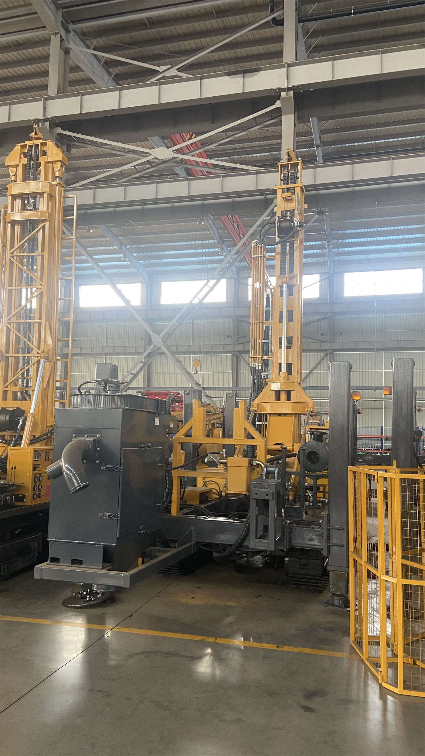
The fast advance speed of 56 m/min and fast lift speed of 29 m/min are another type of value. The data clearly states that these two are more used for power head return, drill pipe operations, and non-drilling actions, and that the actual rock penetration rate depends on the formation, drill bit, DTH hammer, and air compressor capacity. In other words, treating them as drilling efficiency indicators is inconsistent with the original wording of the data. Any change in these three links will cause the actual advance performance to depart from the scenario described by these two values.
Group 7: 8.6 T Overall Machine and 6.25 × 1.7 × 2.39 m Dimensions
The overall machine weight is about 8.6 T, dimensions are about 6.25 × 1.7 × 2.39 m, crawler travel speed is about 3 km/h, maximum climbing angle reference is 21°, and hydraulic outrigger stroke is 1.6 m. These items all belong to the chassis and support conditions: weight and dimensions together determine the transport plan, crawler speed and climbing angle determine the range of internal site transfers, and outrigger stroke determines the leveling margin before drilling. When discussing outriggers, the data suggests using pads on soft ground, and when discussing transfers, it suggests paying attention to ground bearing capacity, slope stability, and transport routes. These three suggestions all point to the same thing—the prerequisite for the above groups of drilling capabilities is that the equipment can stand firmly and be in position.
Group 8: 103 kW Power and Optional Accessories
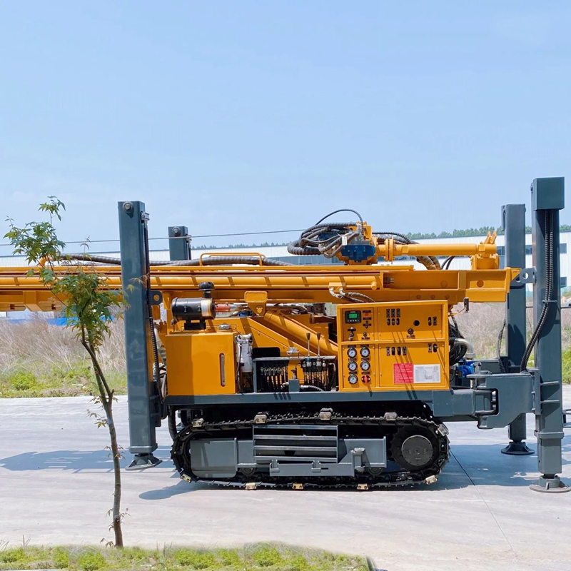
The overall machine uses a 103 kW Weichai engine, providing power for rotation, feed, crawler travel, outriggers, and auxiliary systems; the 1.5 T auxiliary winch is used for handling DTH hammers, drill pipes, casing tools, and other accessories. The data also lists optional mud pumps, centrifugal pumps, generators, and foam pumps, and gives the project types they roughly correspond to: loose layer projects place more emphasis on mud and drainage systems, hard rock projects focus more on DTH hammers and air compressors, and formations with severe air leakage may require foam assistance. The characteristic of this group is "selected according to the project," with no fixed combination.
Comparison of Pairing Relationships Among Several Values
| Value | What to Read It With | Qualification Already Stated in the Data |
|---|---|---|
| 400 m maximum drilling depth | 105–325 mm aperture | Final well depth should be determined in conjunction with local hydrogeological conditions |
| 6 m drill pipe | 89 / 102 mm recommended diameter | The value is mainly reflected in reducing pipe connection frequency |
| 22 T lifting force | 4 T axial pressure | For stuck drilling, hole shrinkage, and wall collapse, first clean the hole and adjust the process |
| 8000 / 4000 N·m | 75 / 150 r/min | Select the working condition according to aperture, drilling tools, and rock formation changes |
| 1.2–3.5 MPa air pressure | 16–55 m³/min air consumption | For large aperture, intact hard rock, and high altitude, check displacement first |
| 56 / 29 m/min | Non-drilling actions | Penetration rate is not determined by these two numbers |
What This Reading Method Does Not Cover
Paired reading can solve "whether the values hold true with each other," but the problems it cannot solve are equally clear: the actually achievable hole depth under different apertures, the displacement range corresponding to a particular DTH hammer, and the process switching points when soil and rock layers alternate are not given as directly quotable corresponding values in the data. These need to be confirmed separately in specific projects according to hydrogeological conditions, drilling tool combinations, and actual air compressor output. The data also states at the end that due to differences in actual geological conditions, downhole tools, drilling angles, and operating methods, the final drilling efficiency, drilling depth, and well completion effect should be based on on-site working conditions.