












A 300 m water well, if the upper part consists of soil and sand layers and the lower part enters weathered rock or intact rock, requires different drilling methods at each end. The WR300SE documentation on this site states it can be used in loose formations and rock, placing one machine into two processes. The real issue to handle on site is not "whether it can drill" but how these stages connect within the same well.
First, where does this equipment's scope of application fall?
The documentation provides fairly specific boundaries: maximum drilling depth 300 m, borehole diameter 105–325 mm, applicable formations listed as loose formations and rock, and application directions including farmland irrigation, rural water supply, livestock water, and groundwater investigation. The equipment is only suitable when these conditions are all met. Taking 300 m alone as a conclusion would miss the constraints imposed by borehole diameter and formations.
In areas with deep groundwater levels and insufficient centralized water supply coverage, the 300 m class offers greater water-finding margin than the 200 m class, but the documentation also notes: before well completion, the target aquifer should be judged based on local hydrogeological data, and it is not recommended to blindly deepen solely based on maximum drilling depth. Depth is the equipment's upper capability limit, not the design target for every well.
The loose layer section: constraints are in the borehole wall, not penetration rate
Soil, clay, sand, and gravel layers are prone to collapse, diameter reduction, and drill burial. The documentation states: in such formations, priority should be given to mud circulation, casing, and borehole wall protection, avoiding the mere pursuit of rapid penetration. In other words, this section controls whether the hole can continue downward, not how many meters per hour are drilled.
Mud pumps and centrifugal pumps are listed as optional items in the documentation, used for circulation, drainage, and auxiliary well completion. Whether to equip them and which type to choose depends on the main drilling method in this section—the documentation does not make this decision for the project.
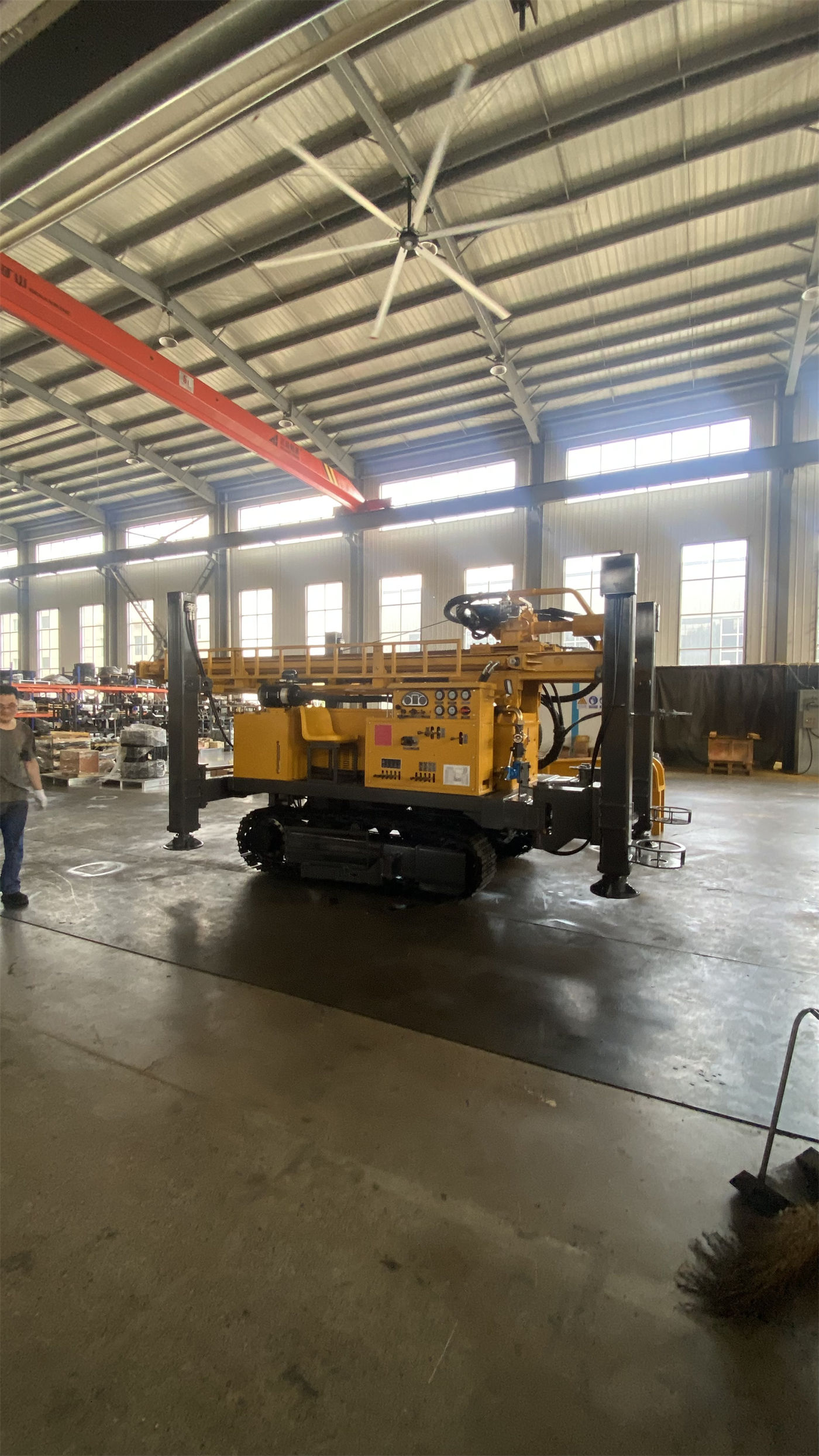
Entering rock: at which step does process switching occur?
The documentation states: "After entering weathered rock or intact rock, DTH hammer drilling can be switched according to lithology." Switching is not pressing a button; it changes the drilling method from mud rotary to pneumatic percussion, and the following must also change: air compressor engagement, DTH hammer and bit replacement, and cuttings discharge method. Among supporting items, a foam pump can be used as an optional system for some pneumatic drilling conditions.
On the pneumatic drilling side, the documentation provides two sets of values that must be read together: recommended working air pressure 1.2–3.5 MPa, air consumption 16–55 m³/min, compatible with medium and high-pressure series DTH hammers. When selecting an air compressor, one cannot look only at pressure but must also consider borehole diameter, drill pipe, DTH hammer specifications, rock hardness, and altitude; insufficient displacement usually directly affects impact efficiency and bottom-hole cuttings discharge.
Why dual-condition torque is listed on one machine
The WR300SE's maximum rotary torque is listed as 7000 / 3500 N·m, corresponding to maximum rotary speeds of 80 / 160 r/min. The documentation explains: the lower speed, high torque state is more suitable for larger borehole diameters and higher load conditions, while the higher speed state can be used for drilling stages with lower resistance. The working range should be selected on site based on changes in drilling tools and rock formations.
Putting this set of values together with the two strata layers above makes them align: the loose layer or small diameter stage has relatively low load, while the rock and large diameter stage has increased load. It is not two speed gears but two working ranges reserved on the same machine.
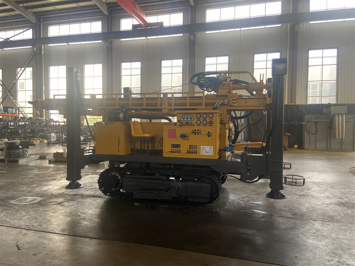
As depth increases, changes in drill string load appear at the lifting end
Lifting force is listed as 15 T, and the documentation states it is used for drill pipe tripping, DTH hammer recovery, and some casing operations. It also provides a limitation: as hole depth increases, both drill pipe self-weight and borehole wall friction increase, and during construction, pull-out resistance should be continuously observed; if obvious abnormalities occur, priority should be given to checking diameter reduction, falling blocks, stuck drill, or cuttings discharge problems, rather than directly relying on maximum lifting force to force handling.
Fast lifting speed 30 m/min and fast feed speed 55 m/min are used for drill pipe handling, power head return, and auxiliary actions. The documentation also gives a reference drilling efficiency of 10–35 m/h and clearly states that actual penetration rate depends on formation, borehole diameter, drilling tools, air compressor, and operation method; fast feed speed cannot be understood as actual drilling speed.
Which set of conditions corresponds to each well section
| Well section | Main constraint | Corresponding values given in documentation |
|---|---|---|
| Upper loose layer (soil, clay, sand, gravel) | Hole stabilization, collapse and diameter reduction prevention | 105–325 mm borehole diameter; mud pump and centrifugal pump optional |
| Transition section (weathered rock) | Process switching, drilling tool replacement | Can switch to DTH hammer drilling; foam pump optional |
| Lower intact rock | Impact efficiency and bottom-hole cuttings discharge | Working air pressure 1.2–3.5 MPa; air consumption 16–55 m³/min |
| Full-well rotary | Borehole diameter and rock load | 7000 / 3500 N·m; 80 / 160 r/min |
| Full-well tripping | Drill string self-weight and borehole wall friction | 15 T lifting force |
Fracture zones and aquifers will rewrite the construction rhythm
The documentation points out that fracture zones, fissures, and local cavities may cause air leakage, falling blocks, and stuck drill; when encountering such hole sections, feed should be reduced, hole cleaning strengthened, and air pressure changes observed, with foam, casing, or other auxiliary methods used if necessary. After entering the main aquifer, return water and cuttings discharge conditions may change significantly; the aquifer depth should be recorded promptly, and air supply, mud, or hole cleaning methods adjusted according to water inflow; during well completion, the filter pipe position and water-stop section must also be determined based on aquifer distribution.
These two types of situations may not occur simultaneously in a 300 m well, but once they occur, the handling method differs from the earlier rhythm of switching by section and belongs to temporary adjustments within a single hole.
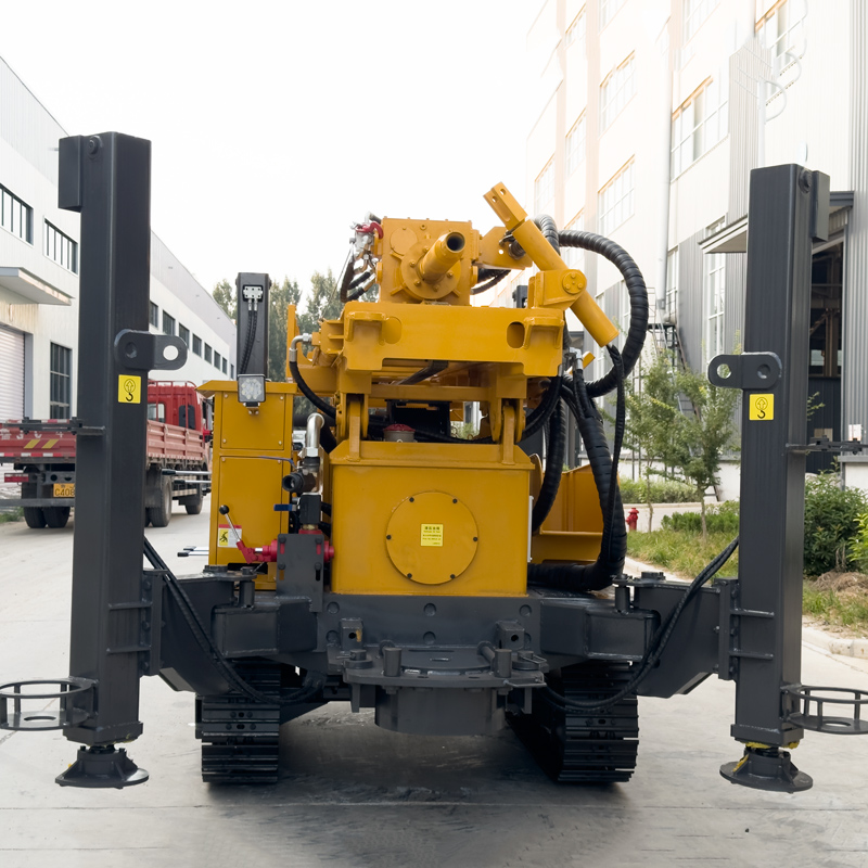
Impact of chassis and power configuration on such wells
Overall weight is about 7.2 T, travel speed 2.5 km/h, and maximum climbing angle reference 21°. The crawler chassis is suitable for rural roads, gravel ground, and generally uneven sites; before moving the equipment, the mast should be retracted and ground bearing capacity confirmed, with greater caution needed on wet slopes and soft soil areas. Hydraulic outrigger stroke is 1.5 m; before formal drilling, ensure the outriggers are evenly loaded, and add pads on soft ground.
Standard engine power is 73 kW, with 85 kW optional, and mud pump, centrifugal pump, generator, and foam pump are also optional. The documentation gives only a principled note on power selection: when conventional borehole diameters and general formations are the main focus, standard power helps control costs; for long-term operation with larger borehole diameters, hard rock, or high-altitude conditions, a higher power configuration can be evaluated. The documentation does not provide a specific table matching working conditions to power, and this part requires independent calculation based on project load.
What conclusions the documentation does not provide
- The actual depth achievable under different formation combinations is not listed by formation in the documentation, only the overall upper limit of 300 m.
- When loose layer and rock each account for what proportion, whether to choose 73 kW or 85 kW is not given as a corresponding relationship in the documentation.
- Specific air compressor models, displacement, and matching plans for each well are not given; the documentation only provides air pressure and air consumption ranges.
- Water yield after well completion depends on aquifer conditions and is not within the scope of equipment parameters.
- Drilling efficiency of 10–35 m/h is a reference value, and the documentation notes that on-site conditions should prevail.
Projects suitable for this equipment are usually water wells with a target depth within 300 m, borehole diameter within 105–325 mm, and inconsistent upper and lower strata; whether a specific well can be completed as expected still requires judging local hydrogeological data together with equipment parameters.