












The WR220SE is classified as a 220 m class mini crawler water well drilling rig, and the documentation lists two features simultaneously: an overall weight of approximately 4.7 T, dimensions of 3950 × 1750 × 2250 mm, and dual water-air drilling. These two are often placed in the same product description, but they do not answer the same question. The chassis dimensions govern whether the equipment can reach the hole position and complete support near it; dual water-air governs which method is used for cuttings removal and rock breaking after entering different formations. Treating them as two ways of saying the same thing will cause one of the prerequisites to be overlooked during selection.
What the Compact Chassis Delivers Is Not Drilling Depth
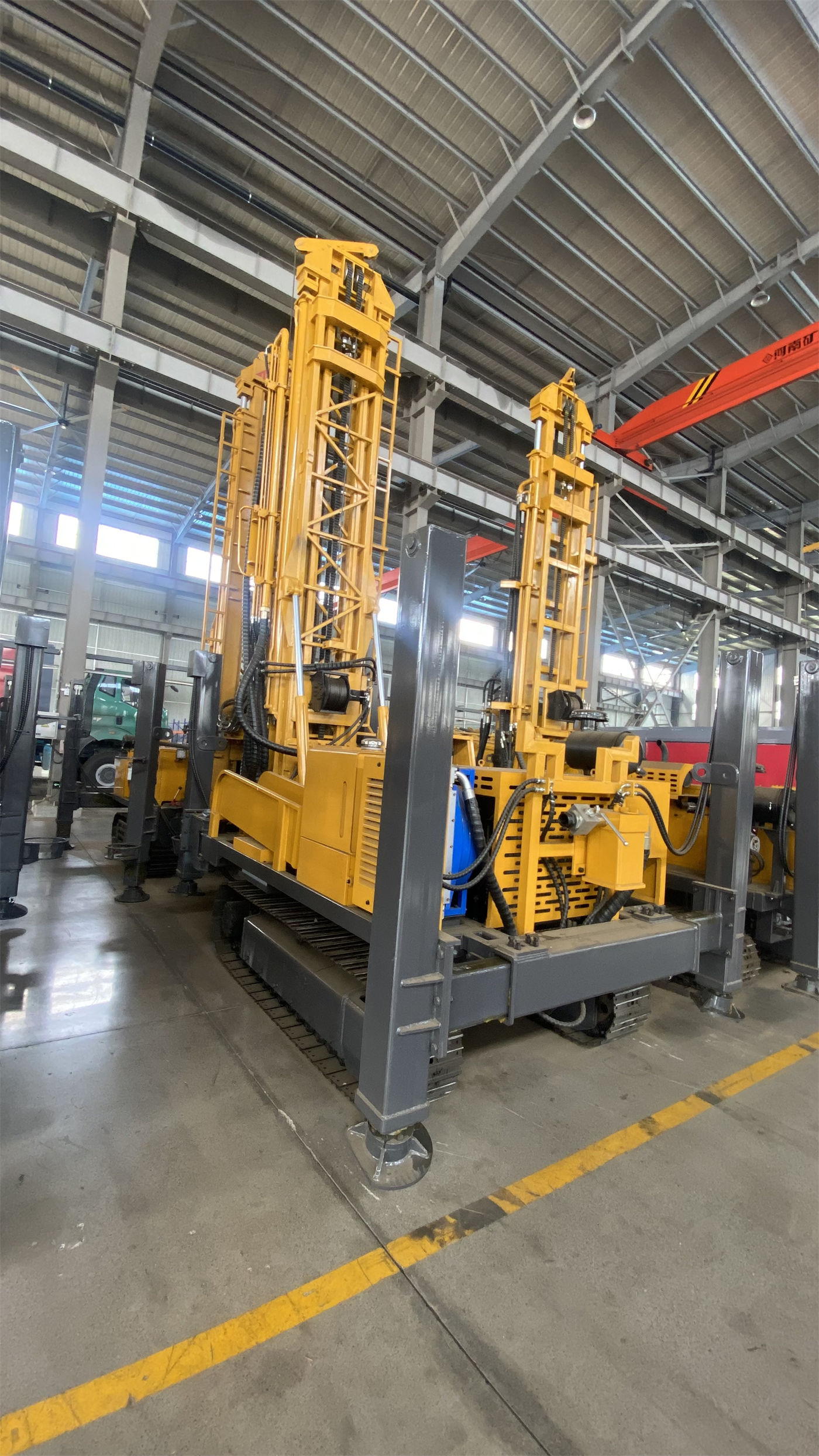
Let's first look at the chassis side separately. Among the WR220SE's nominal parameters, those directly related to "mini crawler" include: dimensions 3950 × 1750 × 2250 mm, overall weight approximately 4.7 T, travel speed approximately 2.5 km/h, maximum gradeability reference 30°, high outrigger stroke 1.4 m, and loading width 2.6 m. These values describe the equipment's passage, support, and relocation conditions, and none directly equals drilling capability.
- Dimensions and weight affect the access path: hole positions on rural roads, orchard passages, farmland edges, courtyards, and within enclosures are more sensitive to transport profile than to drilling depth.
- Travel speed and gradeability affect how to move between hole positions. 2.5 km/h and 30° are reference values; actual relocation depends on ground slipperiness, slope, and whether the mast is in transport position.
- High outrigger stroke of 1.4 m affects leveling. Slightly uneven sites can be compensated by outriggers; soft ground requires pads to prevent outrigger sinking from affecting hole deviation.
In other words: the mini crawler chassis delivers the space to "approach the hole position and position itself by attitude." It does not change drilling indicators such as 220 m drilling depth and 140–254 mm hole diameter; it only gives these indicators a chance to be used in scenarios that were originally difficult to set up.
What Dual Water-Air Delivers Is Formation Adaptability
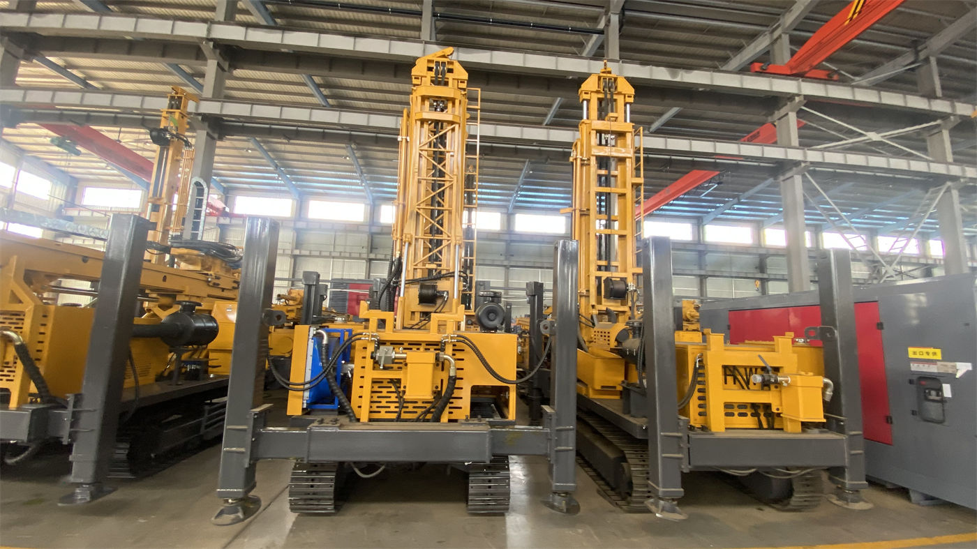
Dual water-air corresponds to another set of stages. The documentation states that this equipment can focus on hole stabilization and cuttings removal in soil, clay, and loose overburden, and after entering weathered rock or relatively intact rock, it can be equipped with a DTH hammer and air compressor for pneumatic drilling. That is, dual-purpose is not about speeding up or slowing down the same procedure, but about changing the rock-breaking and cuttings-removal method according to hole section conditions.
The nominal parameters directly related to pneumatic drilling are: working air pressure 1.7–2.5 MPa, air consumption 17–31 m³/min, and the documentation explicitly states that this item refers to air compressor matching during DTH hammer drilling. When hole diameter increases, rock hardness increases, or altitude rises, the required air compressor displacement will be higher. Two things need to be distinguished here: the existence of the dual-purpose process and whether a suitable air compressor is configured on site are two independent conditions. The equipment supporting a certain method does not mean the supporting equipment is already on site.
Different Hole Sections, Different Focuses of the Dual-Purpose Process
| Hole Section Type | Focus Points Noted in the Documentation | Corresponding Equipment-Side Parameters |
|---|---|---|
| Soil, clay, loose overburden | Hole stabilization and cuttings removal | Water drilling related accessories, casing, etc. |
| Weathered rock, medium-hard rock | Falling blocks, hole shrinkage, water return conditions, control penetration rate | Rotary torque 3400–4700 N·m, rotation speed 45–70 rpm |
| Sand layer, sand-gravel layer | Hole collapse, drill burial, hole diameter enlargement | Hole wall protection and casing follow-up |
| Fracture zone, fissured formation | Air leakage, falling blocks, drill sticking, abnormal cuttings removal | Actual matching of 1.7–2.5 MPa air pressure and 17–31 m³/min air consumption |
The table does not include a column for "which formation is best drilled with which method" because the documentation provides conditions and focus points, not conclusive recipes. Which section uses water and which section switches to air must be judged based on local hydrogeological data, hole wall stability, and on-site supporting equipment.
The Two Features Do Not Act at the Same Stage
Looking at the two parts above together, a relatively clear division of labor emerges: the mini crawler structure constrains equipment arrival and positioning, while dual water-air constrains process selection after entering the formation. They do not substitute for each other—no matter how compact the chassis, it will not make loose layers less prone to collapse; no matter how flexible the process, it will not allow a machine to enter a site it cannot enter.
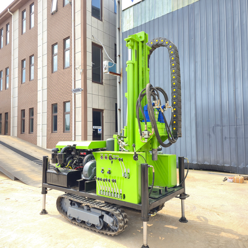
The main nominal parameters directly related to drilling itself in the documentation are: maximum drilling depth 220 m, drilling diameter 140–254 mm, drill pipe diameter Φ76 / Φ89 mm, drill pipe length 1.5 / 2.0 / 3.0 m, lifting force 13 T, mast height 2.6 m, single feed length 3.3 m, engine Yuchai 48 kW. These values fall within the capability range of 220 m class equipment; actual well depth still needs to be determined based on local hydrogeological data and aquifer position, and the 140–254 mm hole diameter selection must also consider well casing specifications, submersible pump size, and expected water yield.
Several Conditions Still to Be Aligned Before and After Selection
- Whether the access path satisfies the 3950 × 1750 × 2250 mm transport profile and 2.6 m loading width; bridges, culverts, width limits, and turning radii along the route need actual measurement.
- What the main formation types are. This determines whether pneumatic drilling accessories are needed, and how casing, filter pipes, and sealing sections are arranged.
- If a DTH hammer is used, whether the air compressor is matched to the reference range of 1.7–2.5 MPa and 17–31 m³/min, with corrections for hole depth, hole diameter, and altitude.
- Whether the well completion stage is part of this equipment's work scope or is completed by separate configuration.
- Whether the specifications of drill pipes, DTH hammers, drill bits, casing, air pipes, oil misters, and other accessories correspond to the main formation and hole diameter.
Not all of these can be answered from product documentation. The documentation provides equipment-side parameters and some applicability descriptions; project-side hydrogeological conditions, surrounding environment of the hole position, and accessory delivery status need to be confirmed separately before selection. In one sentence: the WR220SE's "mini crawler" and "dual water-air" are two capability lines each with their own boundaries. Breaking them apart brings you closer to the role the equipment plays in actual projects than merging them into a single promotional phrase.