












For rural water supply wells, the workload often falls not on the drilling rig itself, but on the earlier steps: where the well is sited, what diameter to drill, how deep the aquifer is, and how the well casing is arranged. Once these items are clarified first, the equipment parameters have something to be checked against. This article uses this site's WR200SE as an example—200 m maximum drilling depth, borehole diameter 140–254 mm, Yuchai 58 kW, lifting force 13 T, reference working air pressure 1.7–2.5 MPa, air consumption 17–31 m³/min—and lists the data and site conditions separately in the order from well siting to well completion. All values in the article are taken from the product information published on this site; they do not involve on-site measurements, nor do they infer conditions that are not stated.
1. First distinguish between "data" and "site conditions"
These two categories are often discussed together, but in fact they solve problems at different points.
- The data side refers to the information on which the determination of well location, well depth, well diameter, and completion structure is based, such as regional hydrogeological conditions, the depth and water yield of existing nearby wells, target water demand, and the approximate location of the aquifer. This information determines the direction in which all subsequent parameters should be configured.
- The site conditions side refers to the part that truly has to engage with the site after the equipment arrives: roads, site levelness, whether there is a stable power supply, water source location, discharge destination for cuttings, and the space around the well location.
The information for this site's WR200SE states that it is suitable for rural water supply, farmland irrigation, livestock water use, and small mining area water well construction, and that it uses a crawler chassis, telescopic mast, and 58 kW diesel power. These descriptions point to the boundaries on the equipment side and cannot replace the former category of data.
2. Several items to be addressed during well siting
Well siting is not just about looking at one piece of terrain
What is usually needed for well siting includes: existing groundwater level data for the area, the approximate depth of the target aquifer, the completion depth and well diameter of existing nearby wells, and the distance and elevation difference between the well and the water use point. The information on this site does not provide hydrogeological data for specific regions; this part must be determined by local hydrogeological data and on-site reconnaissance.
Well depth and well diameter must be determined together
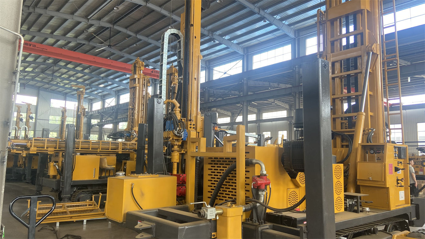
The WR200SE's maximum drilling depth is 200 m, and its borehole diameter range is 140–254 mm. These two values are not independent of each other: the drilling depth is valid only within the diameter range. For the same well depth, different well diameters impose different requirements on lifting force, rotary torque, and air compressor consumption. The information also gives a lifting force of 13 T, rotary torque of 3400–4700 N·m, and rotation speed of 45–70 r/min, all of which must be checked after the well diameter is determined.
3. Hole diameter, well casing, and screen: the completion structure stage
The borehole diameter can only be selected from 140–254 mm, and the dimensions of the well casing and screen must fall within this range. The judgment given in the information for this stage is: for agricultural wells that require long-term pumping, the well diameter, screen, and pump type should be determined in light of the expected water yield, rather than simply pursuing a larger hole diameter.
The data to be prepared for this stage roughly includes:
- Expected water yield and pumping method, used to work backward to well diameter and pump type;
- Well casing material, diameter, and casing running depth;
- Whether the screen opening positions correspond to the aquifer depth;
- Sealing position and sealing material.
For the above items, the information gives only directional descriptions; the specific structure must be determined according to local hydrogeology and water use needs, and cannot be derived solely from the equipment parameter table.
4. Hole stabilization materials and casing: handle the upper hole section first
The information contains a clear statement about the construction sequence: in upper soil layers, clay, sand layers, or gravel layers, directly using a down-the-hole hammer is not necessarily the best solution. Loose overburden is prone to hole collapse, drilling tool burial, and hole diameter enlargement, so casing, mud, or other hole stabilization methods should be used to handle the upper hole section first before continuing drilling into stable rock formations.
According to this description, what needs to be arranged in advance on site is: casing specifications and quantity, mud materials or hole stabilization methods, simultaneous casing tools, and the corresponding time schedule for running and pulling casing. This stage is a construction organization issue; the information on this site does not provide a specific process plan, and it must be determined separately according to actual formation conditions.
5. Drilling tools and air compressor: parameters must be checked as a group
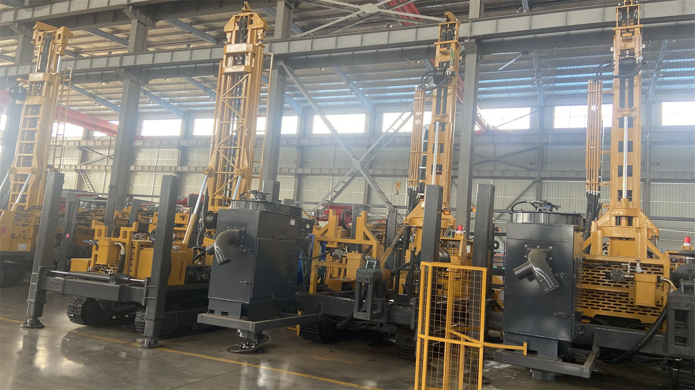
The values related to this part in the WR200SE information are listed in the table below.
| Item | Information value |
|---|---|
| Drill pipe diameter | 76 / 89 mm |
| Drill pipe length | 1.5 / 2.0 / 3.0 m |
| Single advance length | 3.3 m |
| Reference working air pressure | 1.7–2.5 MPa |
| Air consumption | 17–31 m³/min |
| Reference drilling efficiency | 10–35 m/h |
The information's explanation of air compressor matching is: the air compressor should be selected according to hole diameter, down-the-hole hammer specifications, target hole depth, altitude, and rock hardness. When the hole diameter increases, the rock formation becomes harder, or the altitude rises, a more sufficient displacement is usually required. Therefore, this item should not be selected based on a single value in the table, but should be viewed together with several conditions.
The reference drilling efficiency of 10–35 m/h is a reference value in the information; actual penetration depends on lithology, the down-the-hole hammer, the drill bit, and air compressor capacity, and should not be directly converted into the construction period of a particular well.
6. Site, road, and power conditions
The WR200SE has a crawler chassis, an overall weight of about 4.7 T, overall dimensions of about 3950 × 1750 × 2250 mm, a travel speed of about 2.5 km/h, a maximum gradeability reference of 30°, and 1.4 m high outriggers for leveling. The information's description of the site is: the crawler structure is suitable for rural roads, farmland, gravel sites, and mildly uneven ground.
Putting this stage into on-site preparation corresponds to:
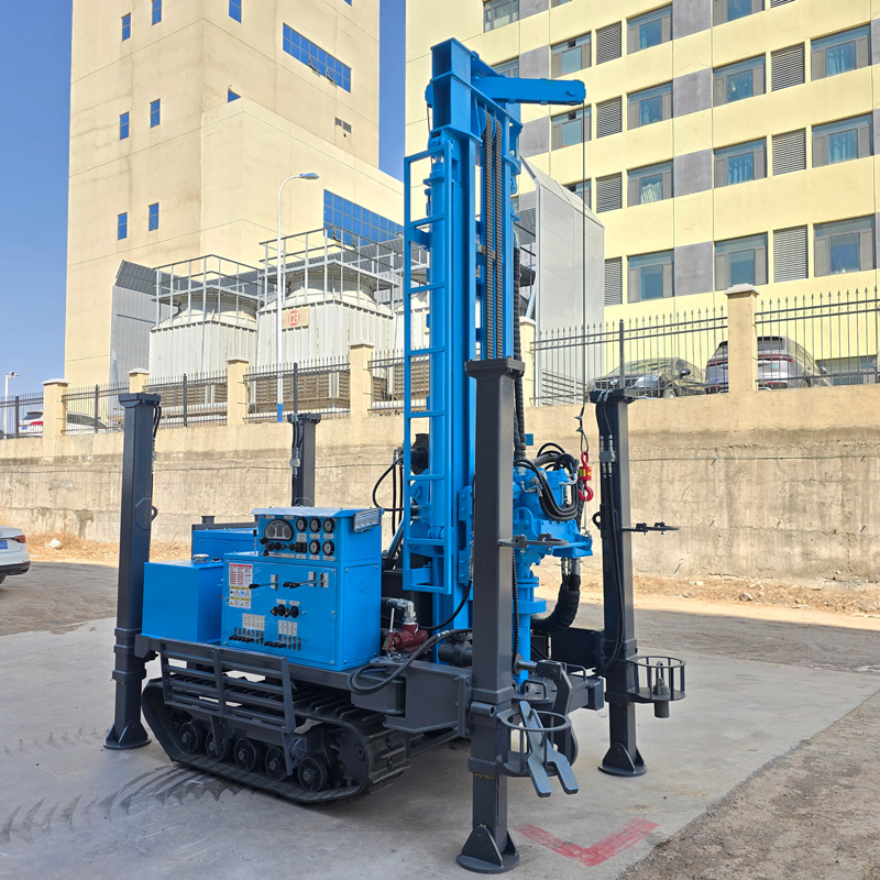
- Access road width, load-bearing capacity, and turning conditions, and whether the crawler can travel on its own or needs to be transported by truck before traveling;
- Whether the area around the well location can accommodate the crawler chassis and complete outrigger leveling, and whether soft ground needs mats;
- 58 kW diesel power means it does not rely on a fixed power supply, but the supply method for fuel and engine oil must be arranged in advance;
- The destination for cuttings, mud, and cleaning water;
- The relationship between the well location and the water use point and pump installation position.
The crawler chassis is suitable for rural roads and generally unpaved sites; this is an applicability description and does not mean it can enter all field ridges and slopes. Specific passage conditions must be judged according to the actual road surface.
7. Pre-drilling inspection items
The daily inspection scope listed in the information is: hydraulic lines, rotary head, winch, crawler, mast, and drill pipe connections; for the air compressor and high-pressure air hose, check joints and safety devices. During construction, continuously observe air pressure, cuttings discharge, water return, and equipment temperature; after completion, clean mud and dust and inspect wearing drilling tools.
These are equipment-side inspection items. For content involving specific operating steps and safety protection, the information on this site does not provide complete regulations; it should be carried out in accordance with the equipment's accompanying documents, on-site management regulations, and operating procedures.
8. Which conditions still need separate on-site confirmation
- The actual depth of the aquifer and expected water yield need to rely on local data and records during well completion;
- The thickness of the upper loose layer and whether simultaneous casing is needed must be judged according to actual in-hole conditions;
- The final air compressor displacement and the combination of down-the-hole hammer and drill bit must be calculated according to target hole diameter, rock hardness, and altitude;
- The specific dimensions of the well casing, screen, and sealing structure;
- Coordination matters between the well location and surrounding facilities and land use.
The information contains a general statement: because actual geological conditions, in-hole tools, drilling angle, and operating methods differ, the final drilling efficiency, drilling depth, and well completion effect should be based on on-site working conditions. This statement also applies to the preparation items listed in this article: they are a checklist sequence, not a well completion plan that can be directly applied.