












The number 1500 m appears on the first line of the WR1500S specifications, but the same section also contains a second number: hole diameter 105–1000 mm. Placed together, whether the actual well diameter falls at 105 mm or one meter determines that the drilling tools, casing, air compressor, and lifting load are completely different in magnitude. What truly needs to be determined first in deep hole selection is hole diameter and completion objectives; drilling depth is the upper limit confirmed only after these are established.
First Branch: Narrow Down the Hole Diameter First
The 105–1000 mm range is very wide, so wide that it cannot be treated as a fixed output of one machine. As hole diameter increases, the annular volume in the hole, cuttings return volume, casing specifications, and rotational resistance all increase simultaneously; as hole diameter decreases, the available space for filter pipes and pump types also shrinks. The specifications give the diameter range the equipment can cover, but which one is actually used in a project must be back-calculated from the completion objectives.
- Conventional deep water wells: The completion structure determines the filter pipe and well casing diameters, and the hole diameter must leave annular clearance for this.
- Large-diameter groundwater wells and mine dewatering: Large hole diameter simultaneously raises requirements for rotary torque, lifting capacity, and air compressor displacement.
- Some large engineering holes: The purpose of the hole type differs, and whether it falls within the applicable range of this equipment must be confirmed separately according to the project design.
If this step is not completed, later judgments about torque and lifting force lack a reference frame.
Second Branch: Completion Objectives Determine Which Process Segment to Use
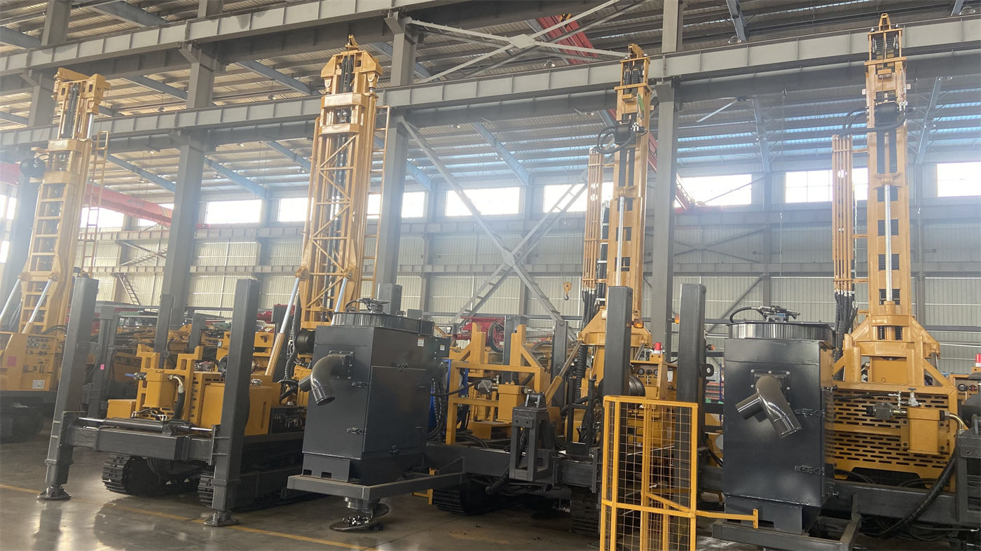
The drilling methods listed in the WR1500S specifications are not a single type, but commonly divided into three categories: mud rotary for loose formations such as soil, clay, sand, and gravel layers; DTH hammer for weathered rock, fractured rock, and intact hard rock; top drive hydraulic rotary for conventional deep water wells and large-diameter drilling. These three are not mutually exclusive options, but are segmented along the hole depth direction.
| Hole Section | Common Process | Completion Concerns |
|---|---|---|
| Upper overburden | Mud rotary, casing wall protection | Hole wall stability, prevent diameter reduction and collapse |
| Middle and lower rock layers | Medium-high pressure DTH hammer | Continuous cuttings return, air pressure and displacement both satisfied |
| Aquifer section | Adjust air supply and hole cleaning according to water inflow | Record depth of water-producing layers, position of filter pipes and sealing sections |
Different completion objectives mean different segmentation positions. For deep aquifer wells, the focus falls on deep rock layers and aquifers; even if the upper overburden section is short, a stable hole body must still be established first, otherwise the subsequent 1500 m construction will be delayed from the opening stage.
After Hole Diameter Is Determined, Check Three Sets of Values
Among the published specifications of the WR1500S, three sets are directly linked to hole diameter and need to be viewed together rather than judged individually.
Lifting Force and Axial Pressure
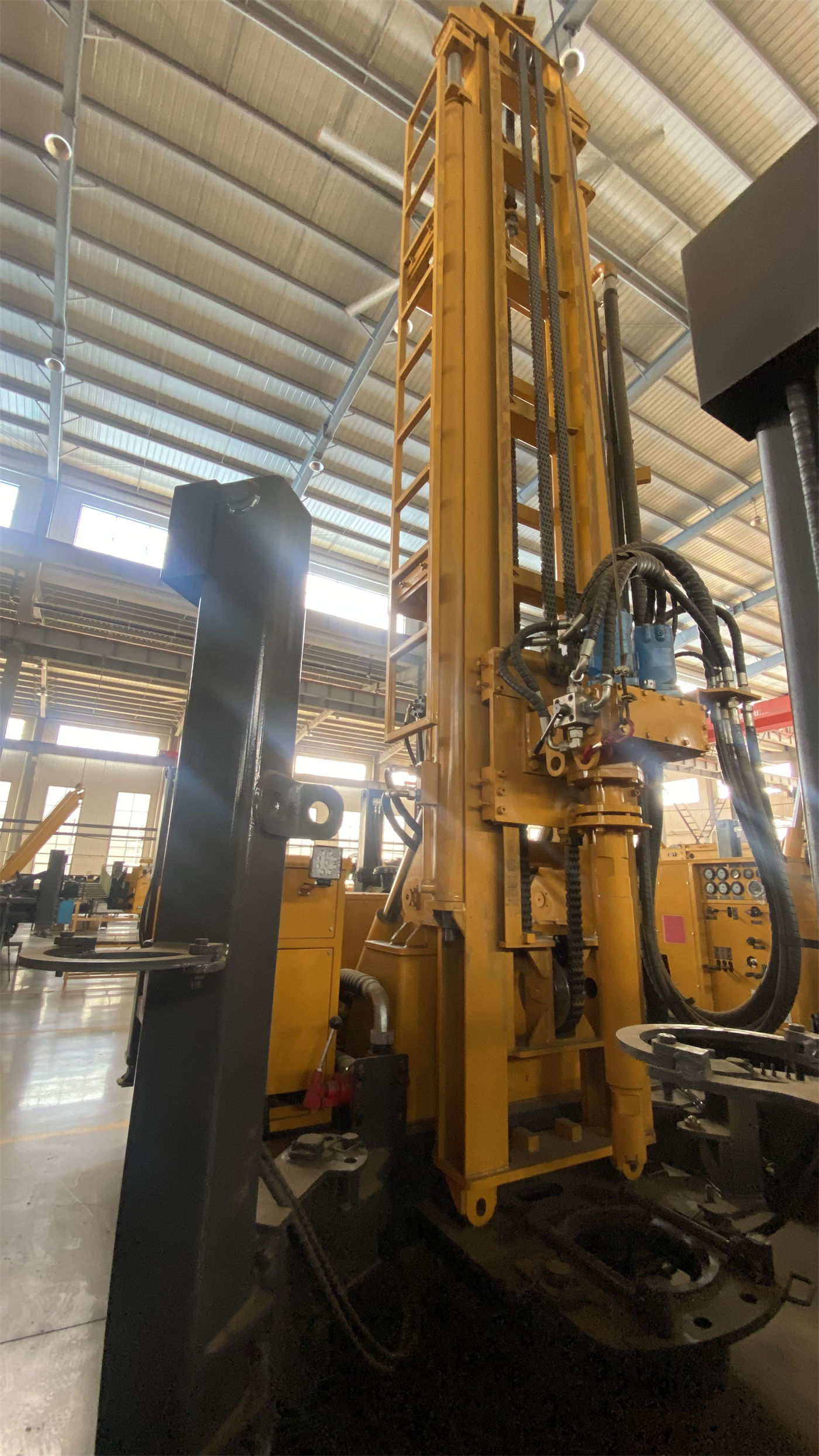
80 T lifting force, 16 T axial pressure. The deeper the hole, the greater the drill string weight, hole wall friction, and casing weight, and the more obvious the load on the lifting section. 80 T provides margin, not a solution for abnormal downhole resistance—the specifications also state that when abnormal resistance occurs, priority should be given to hole cleaning, slow lifting, and judging downhole conditions.
Rotary Torque and Rotation Speed
Maximum rotary torque 31000 / 15500 N·m, maximum rotation speed 70 / 140 r/min. The low-speed high-torque setting is more suitable for large-diameter, hard rock, and high-friction hole sections; the higher speed setting is suitable for stable hole sections with relatively low resistance. The larger the hole diameter, the more it tends toward the former setting.
Drill Pipe Length and Diameter
Supports 9.6 m drill pipes, recommended diameter 114 / 127 mm. A 1500 m hole depth means many pipe connections, and longer drill pipes reduce connection frequency while requiring matching on-site operating space and drill pipe handling organization. Drill pipes usually need to be transported separately.
Air Compressor Section: Air Pressure and Displacement Must Both Be Satisfied
During DTH drilling, recommended working air pressure is 1.65–8 MPa, air consumption 16–120 m³/min. Deep holes plus large diameters are working conditions where both numbers increase simultaneously. Satisfying only pressure may result in insufficient cuttings removal; satisfying only displacement may result in insufficient impact. The specifications state that 'pressure and displacement must simultaneously meet the needs of the DTH hammer and bottom-hole cuttings removal,' otherwise insufficient impact, difficult cuttings removal, and bottom-hole cuttings accumulation are likely.
Construction Rhythm Rewritten by Loose Layers, Fracture Zones, and Aquifers
The specifications give treatment directions for three types of conditions: for weathered rock, fractures, or fault fracture zones, reduce penetration rate, strengthen hole cleaning, and use casing, foam, or other hole stabilization measures as actually used; for loose overburden, prioritize hole wall stability before entering rock layers and switching to DTH; after entering the main aquifer, water inflow will change downhole cuttings removal and DTH hammer working conditions, so record the depth of water-producing layers and adjust air supply, hole cleaning, and casing methods according to water volume. These three are constraints at the construction organization level and cannot be replaced by a parameter table.
Site Entry Conditions Brought by the 28 T Overall Weight
Overall weight approximately 28 T, dimensions approximately 11.5 × 2.6 × 3.5 m, telescopic mast can improve the overall profile in transport condition. Travel speed 3.5 km/h, maximum gradeability 21°. For cross-regional transportation, confirm in advance the flatbed load capacity, road height limits, bridge load capacity, and turning space; after arriving at the site, also reserve areas for the air compressor, mud system, drilling tools, and materials. Dual auxiliary winches (5 T large winch, 2.5 T small winch) are used for handling tools and accessories; lifting still follows rated load and safety distances.
Items Requiring Separate Confirmation from the Manufacturer or Project Owner
- Actual well depth: The specifications state that it should still be determined based on hydrogeology, hole diameter, drill pipe, air compressor, and completion design. 1500 m is the equipment capability upper limit, not the target depth for every well.
- Completion structure: Filter pipes, sealing sections, and final pump type fall within the scope of completion design and need to be designed separately according to aquifer distribution.
- Drilling efficiency: Reference drilling efficiency 10–35 m/h, actual conditions on site prevail, with obvious differences in different formations.
- Optional items: Mud pump, centrifugal pump, generator, and foam pump are optional accessories; whether to equip them and specific specifications need to be confirmed according to project conditions.
- Geothermal projects: If formal geothermal development wells are involved, drilling tools and completion systems should be configured according to special design; equipment specifications are not sufficient to replace that design.
Looking at the sequence in reverse makes it clearer: drilling depth is the result, hole diameter and completion objectives are the branches starting from the premises, and process, air compressor, drill string, and site conditions are supporting items on this branch. If any one of these is not implemented, the 1500 m upper limit is just a number in the specifications.