












In the publicly available documentation for the WR1200SL, 30000 / 15000 N·m and 60 T appear near the same paragraph. The former belongs to the rotation system, the latter to the lifting system. Recorded separately, these two sets of values appear to be two independent capabilities; placed in a 1200 m class deep hole, they correspond to two loads borne by the same drill string—the torque required to rotate it, and the pull required to lift it out of the hole. Neither one alone is sufficient to judge whether the in-hole configuration is viable.
This article reads the WR1200SL parameters already published on this site along these two load lines. The values involved include: maximum drilling depth 1200 m, hole diameter 105–900 mm, rotary torque 30000 / 15000 N·m, corresponding rotation speeds 85 / 170 r/min, lifting force 60 T, axial pressure 10 T, recommended drill pipe diameter 114 / 127 mm, support for 9.6 m drill pipes, and 264 kW Cummins diesel power. It does not involve on-site measurements, nor does it infer in-hole conditions not stated in the documentation.
The rotation end: dual-condition torque corresponds to two speed ranges
The documentation presents rotation as two sets of numbers: 30000 N·m with 85 r/min, and 15000 N·m with 170 r/min. These are not two speed gears that can be switched at will, but a paired relationship between torque and rotation speed—the gear with higher torque has lower speed, and the gear with higher speed has lower torque. The presence of such a pairing on the same machine indicates that the rotation system must cover two different drilling conditions.
Conditions requiring higher torque are typically those with larger hole diameters, higher friction in the hole section, or more intact rock formations. Those requiring higher rotation speed are generally drilling stages with lower resistance. If the 15000 N·m gear is understood as "reducing torque to increase speed," continuing to rotate in this gear when in-hole friction rises will feed the rotational load directly back to the drilling tools.
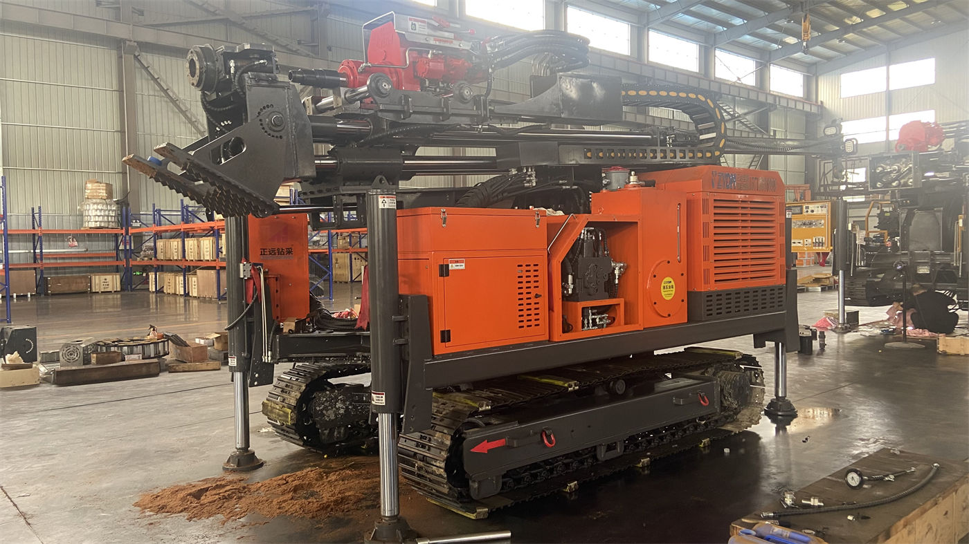
The dual-condition torque values alone cannot yet be used to judge whether the equipment is sufficient. The same 30000 N·m, paired with a 9.6 m long drill pipe versus a short drill pipe, results in different torsional conditions actually experienced in the hole; as the hole diameter goes from 105 mm to 900 mm, the rotational load corresponding to the same torque also differs. The documentation places the 105–900 mm hole diameter range and this set of torque values in the same document, so they should be read together when making comparisons.
The lifting end: what weights does 60 T face
Lifting force 60 T and axial pressure 10 T appear close together in the documentation, but they act in opposite directions. 60 T governs pulling up, while 10 T governs pushing down. At a 1200 m class hole depth, the drill string's own weight, hole wall friction, and casing weight combine, and the pull load increases section by section with hole depth; 60 T provides the margin on this load line.
The documentation also states a boundary: when sticking or hole shrinkage occurs, the hole should first be cleaned and the in-hole condition assessed. This statement frames the applicable scope of 60 T within normal tripping, DTH hammer recovery, and large-diameter casing operations, and does not treat the maximum lifting force as a means of handling in-hole anomalies. No matter how large the lifting force, if the cause of the drill string being stuck in the hole is not resolved, the upward pull can only increase the burden on the drill string and equipment.
How the two sets of values constrain each other at 1200 m hole depth
Rotation and lifting are not two unrelated matters in the hole. The greater the torque when the drill string rotates, the higher the hole wall friction, and the greater the resistance that often must be overcome when pulling up; conversely, if the drill string condition is unstable during lifting, the load will also change when rotation resumes. Placing 30000 N·m and 60 T together shows that the document author presented these two lines as one set of load conditions.
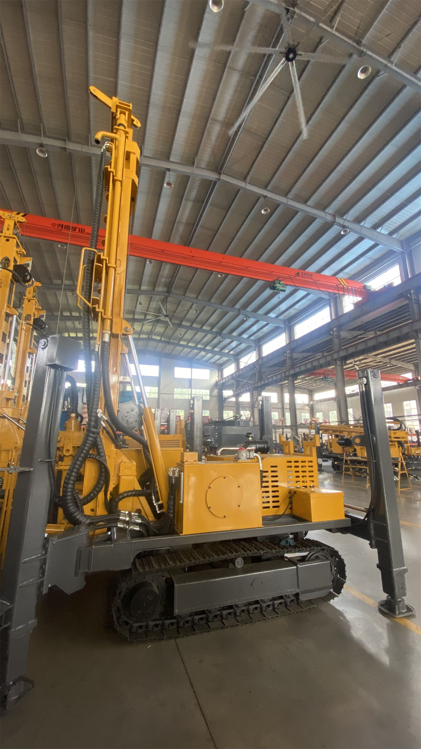
This is also why looking at 60 T alone cannot determine whether the lifting configuration is appropriate: if the rotation torque end remains in the high-load gear for a long time and the hole diameter is chosen at the larger end, the accumulation of in-hole friction will also be reflected in the pull load. The two values must be matched to the same well, the same set of hole diameters, and the same drilling tools.
Other parameters appearing alongside these two sets of values
The documentation also includes several items directly related to rotation and lifting:
- Drill pipe: supports 9.6 m drill pipes, recommended drill pipe diameter 114 / 127 mm. At deep hole depths, the number of pipe joints directly affects auxiliary time.
- Fast lifting 29 m/min, fast feed 51 m/min, corresponding to non-drilling actions such as power head return and drill pipe handling.
- For pneumatic DTH drilling, reference working air pressure 1.65–8 MPa, air consumption 16–120 m³/min, related to rock formation and bottom-hole cuttings removal, and does not change the load relationship between rotation and lifting.
- 264 kW Cummins diesel power, providing power for rotation, feed, travel, outriggers, and auxiliary systems.
The parts not stated in the documentation include: specific rotation load curves under different hole diameters, and the segmented weight of the drill string at different hole depths. These need to be calculated separately during the project design stage and cannot be directly derived from 30000 / 15000 N·m and 60 T.
According to this reading approach, which questions still cannot be answered
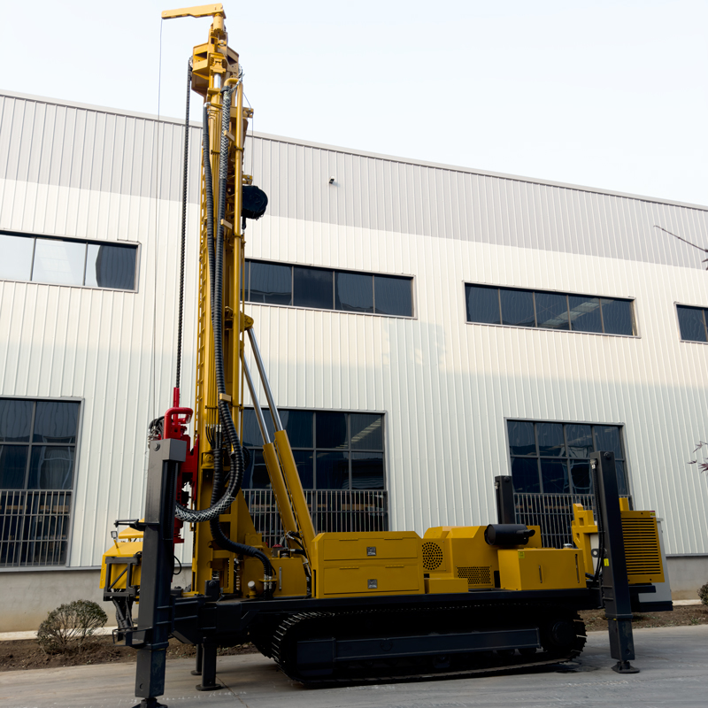
After reading the two sets of values together, what can be determined is the respective ranges covered by rotation and lifting, and that they need to be configured together with hole diameter, drill pipe, and hole depth. At least several items cannot be determined:
- Whether 30000 N·m is sufficient under a specific hole diameter—this depends on the rock formation and bit type, and the documentation does not provide corresponding values by hole diameter.
- How much margin 60 T represents in the actual pull load of a given well—this requires specific data on drill string weight, casing weight, and in-hole friction.
- Under what conditions the dual-condition torque is switched during actual drilling—the documentation provides two paired values but does not state the switching criteria.
These items are all conditions that need to be supplemented and verified during the project design stage. 30000 / 15000 N·m and 60 T can serve as a starting point for reading WR1200SL documentation, but a starting point is not a conclusion.
The significance of writing the two sets of values on one line
Looking only at 30000 N·m, one might think this is a machine that emphasizes torque alone; looking only at 60 T, one might think the focus is on pulling capability. Presenting the two sets of values together shows that a 1200 m class deep hole requires rotation and lifting to hold true simultaneously—if torque is sufficient but lifting is insufficient, deep-hole tripping will be limited; if lifting is sufficient but torque is insufficient, large-diameter sections will be difficult to advance. Reading them in the same section of documentation is precisely how the parameter table of this machine is organized.