












In engineering contexts, the first association with a DTH drill is usually slope anchoring, which is related to the ordering in the DTH30C product documentation—slope anchor bolt holes and anchor cable holes are listed on the first line of typical uses. However, the same documentation also lists three other uses after anchoring: foundation pre-drilling, quarrying, and road engineering. Looking at these three separately, they share the same equipment but each imposes different requirements on parameters: foundation pre-drilling focuses on hole depth and integration with subsequent processes, quarrying focuses on rock hardness and frequency of hole position adjustment, and road engineering focuses on relocation and site conditions.
This article does not repeat the existing description of slope anchoring; it only addresses a scope question: for these three uses of the DTH30C, which conditions are already given by the documentation, and which are not specified and need to be confirmed on a project-by-project basis.
First, look at the equipment's capability values themselves
Before discussing applicability, the constraints need to be listed clearly. The following are values directly related to use from our site's documentation:
| Parameter | Documented Value |
|---|---|
| Maximum drilling depth | 30 m |
| Drilling diameter | 76–280 mm |
| Applicable rock hardness | Medium to high hardness, approximately f=8–24 |
| Maximum rotary torque | 3500 N·m |
| Reference air consumption | Approximately 8 m³/min (original marked as 8 m²/min) |
| Mast travel / effective travel | 3.2 m / 2.2 m |
| Piling height | 2.2 m |
| Swing angle / tilt adjustment | 18–180°, with tilt adjustment function; angle range not given |
| Overall weight / dimensions | 2500 kg / 3200 × 1200 × 1850 mm |
These values are the starting point for judging applicability. It should be noted that the documentation also states that actual drilling efficiency is affected by rock hardness, hole diameter, DTH hammer specifications, air compressor capacity, and bit wear. Therefore, the following discussion is about whether conditions are met, not about efficiency levels.
Foundation pre-drilling: constraints lie in hole depth and subsequent processes
The documentation describes foundation pre-drilling as follows: in equipment foundations, guardrail piles, short piles, and hard rock foundation construction, when encountering intact rock strata, DTH drilling can first be used to form pre-drilled holes, reducing resistance for subsequent piling or installation. The 3.2 m mast travel and 2.2 m effective travel are suitable for medium-short drill rods and short pile construction.
There are two layers of constraints to examine separately.
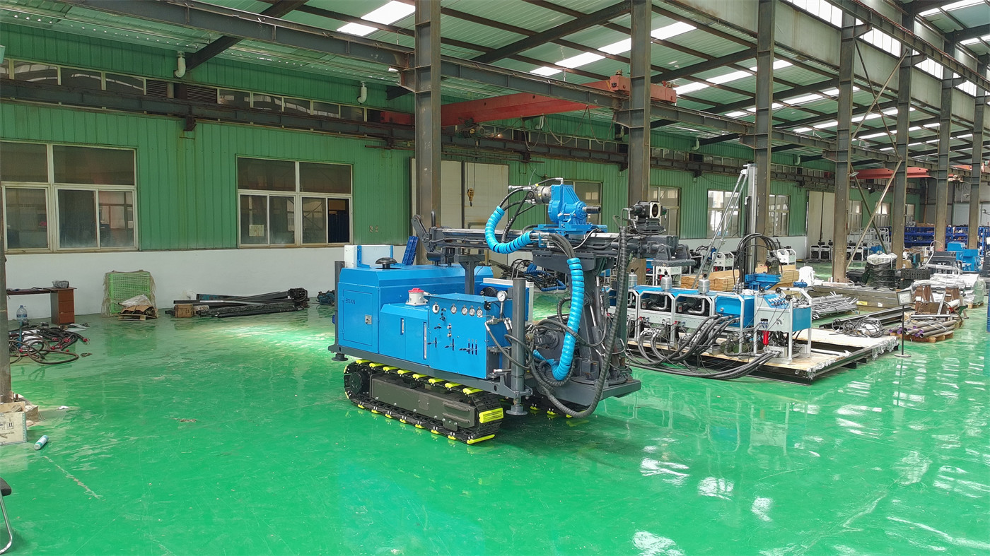
The first layer is depth. The 30 m maximum drilling depth is the equipment limit, but the actual hole depth for foundation pre-drilling is often determined by the pile type or foundation design. The documentation does not provide a recommended depth range for foundation pre-drilling, so which depth range is more cost-effective needs to be calculated based on the specific pile type and cannot be directly derived from the 30 m upper limit.
The second layer is the correspondence between hole diameter and pile type. The 76–280 mm given in the documentation is the equipment's drillable diameter range, but the pre-drilled hole diameter must serve subsequent piling or installation and is a design input, not an equipment selection input. The piling height in the documentation is 2.2 m, which is consistent with the effective travel value and can serve as a reference for integrating pre-drilling with subsequent processes, but it does not mean it is applicable to all pile types.
Quarrying: rock hardness and hole position adjustment frequency are the two main lines
The documentation states that the equipment can be used for bench holes, auxiliary rock breaking holes, and local engineering holes in quarries, stone yards, and open-pit projects, and specifically mentions that it is more suitable for construction environments with narrow sites, shallow hole depths, and frequent hole position adjustments, especially for small and medium-sized engineering teams.
The item "medium to high hardness, approximately f=8–24" is more critical in quarrying scenarios than in slope anchoring. The limestone, granite, sandstone, and basalt listed in the documentation all fall within this range, but the integrity and abrasiveness of the same rock type vary greatly. The documentation states: in actual construction, DTH hammers and bits should be selected according to rock integrity, abrasiveness, and drilling diameter; under hard rock conditions, compressed air supply and DTH hammer lubrication must be ensured. In other words, the f value only frames the broad category; the documentation does not provide a corresponding table for which hammer or bit to use, and this is part of what needs to be confirmed on a project basis.
The capability corresponding to "frequent hole position adjustment" mainly lies in the crawler chassis and overall dimensions. The machine weighs 2500 kg and is about 1.2 m wide. The documentation says it is suitable for some factory areas, enclosed construction sites, and narrow construction passages, but before entering the construction point, turning space, ground bearing capacity, underground pipelines, and surrounding buildings should still be confirmed. These are site conditions, not equipment parameters, and the documentation lists them as items to verify before entry.
Road engineering: crawler mobility provides short-distance movement capability
The documentation's description of road engineering includes slope reinforcement, drainage holes, rock excavation preparation, and guardrail foundations. The crawler chassis facilitates short-distance movement of the equipment along construction access roads and has better traction than wheeled equipment on gravel, compacted soil, and mildly uneven sites; rubber tracks are friendlier to finished pavement and concrete surfaces, making them suitable for urban construction and industrial plants.
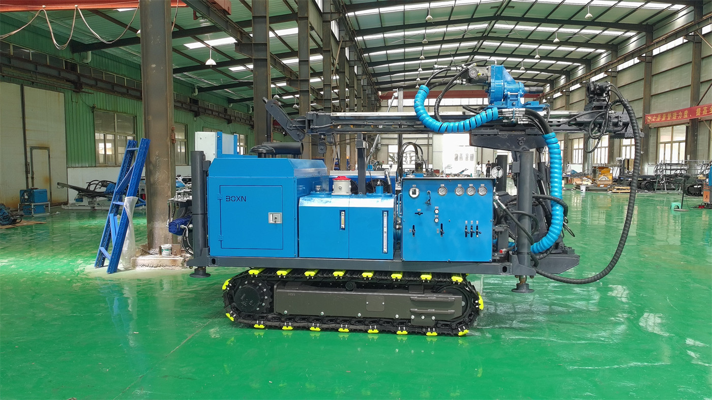
Two things need to be separated here. Rubber tracks reduce damage to finished pavement, but that does not mean the machine can travel directly on any surface; the documented travel speed is 5–10 km/h, and the applicable ground is stated as compacted soil, gravel roads, construction access roads, and general uneven sites. In other words, these ground types are the boundary of this equipment's travel conditions; the documentation does not cover ground beyond this description (such as soft mud or large loose rock).
A constraint shared by all three uses: drilling diameter and rock hardness
The hole diameter range of 76–280 mm and the hardness range of f=8–24 are the shared boundaries of these three uses. Looking at the two ranges together, a question arises that the documentation does not directly answer: when the hole diameter approaches the upper limit and rock hardness also approaches the upper limit, do the 3500 N·m rotary torque and approximately 8 m³/min reference air consumption still match?
The documentation's statement on torque is: it can meet the DTH drilling needs of most 76–280 mm engineering holes; in actual construction, rotation, feed, and impact should remain matched; if rotational resistance continues to increase, return cuttings decrease, or the bit jumps noticeably, parameters should be adjusted promptly and the hole cleaned. This passage gives a direction for judgment, not a matching table. Whether they match depends on the DTH hammer specifications and air compressor capacity, and these two items are listed as optional accessories in the documentation without specific models.
The air compressor section: one notation in the documentation needs confirmation
DTH drilling relies on compressed air to drive the DTH hammer and discharge cuttings, so air consumption directly determines whether the DTH hammer can work properly. The reference air consumption in the documentation is written as approximately 8 m³/min, but the original table actually marks it as 8 m²/min; our site interprets it as m³/min according to the common unit for compressed air flow and notes that the final value should be confirmed with formal technical documentation.
This is an item that this article cannot resolve for the reader. Since this value directly relates to air compressor selection, during project inquiry or technical confirmation, the unit and value of air consumption should be listed separately and verified with the manufacturer; it should not be directly applied based on the existing text.
Site and transport conditions: actual limits corresponding to 2500 kg
The machine weighs about 2500 kg, making it easier to transport and load/unload than large DTH equipment, and it is also suitable for frequent relocations within a construction site. The documentation also gives transport precautions: choose vehicles and fixing points with matching load capacity, ensure loading ramps have sufficient bearing capacity, and prevent the tracks from slipping sideways during loading and unloading.
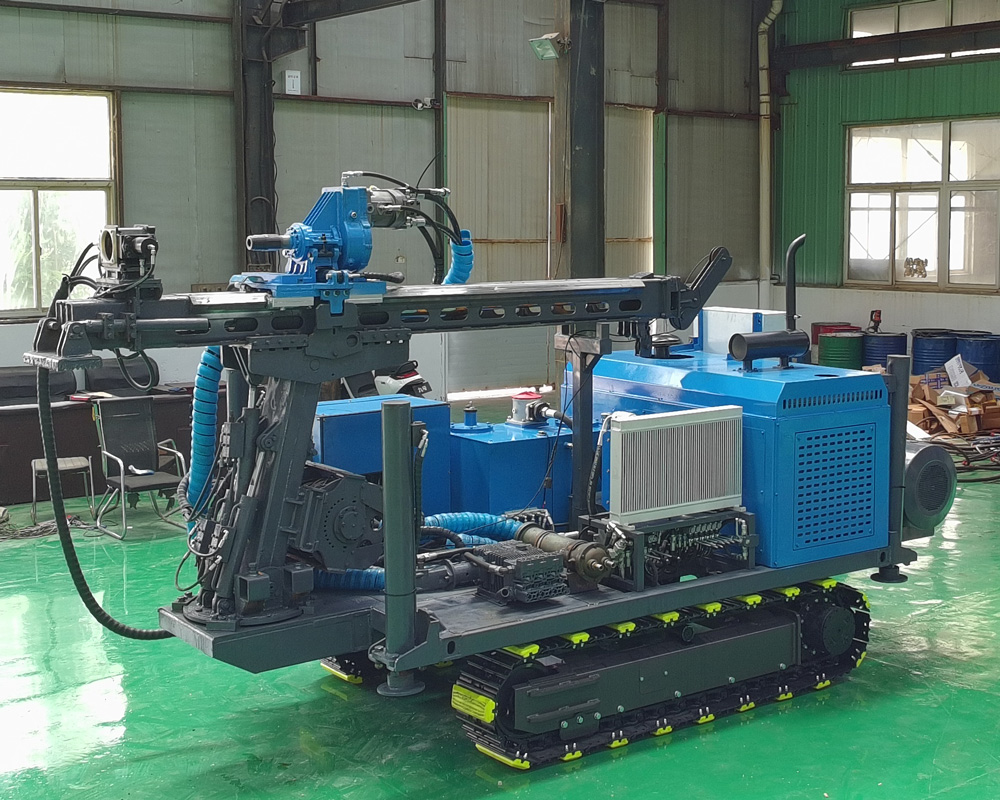
The width of about 1.2 m in the dimensions 3200 × 1200 × 1850 mm is the direct basis for judging whether it can pass through factory passages and enclosure entrances. However, whether a passage can be passed depends not only on width but also on turning radius, ground bearing capacity, and overhead clearance; the documentation does not provide corresponding values for these items.
Several boundaries already stated in the documentation and relevant to the scope of this article
- The 30 m maximum drilling depth makes it closer to engineering hole equipment than deep water well equipment. The documentation clearly states that for deep water wells of 200 m, 300 m, or more, dedicated water well drilling rigs should be used.
- The tilt adjustment function is stated as available, but the documentation does not give a specific angle range. Project design should be based on the final production configuration and technical confirmation documents.
- Weathered rock, soil-rock mixed layers, and upper loose overburden are prone to unstable hole walls. The documentation recommends reducing feed speed and using casing, starting drilling tools, or other upper hole stabilization methods as needed.
- Fractures and broken zones are prone to block falling, air leakage, and sticking. The documentation recommends reducing excessive feed, maintaining continuous hole cleaning, and if high-pressure air circuit pressure is abnormal or return cuttings suddenly stop, drilling should be stopped first for inspection.
- The feed speed of 53 m/min is the rapid movement speed of the feed mechanism, used for power head return, drill rod handling, and non-drilling actions, and cannot be directly understood as rock penetration rate.
Questions this article cannot answer
The first is efficiency values. The documentation does not provide penetration efficiency under any formation conditions, nor comparative data for different hole diameters and DTH hammer specifications. This article makes no speculation.
The second is accessory models. DTH hammers, bits, drill rods, casing tools, air compressors, high-pressure air hoses, oil mist lubricators, dust collectors, or water mist dust suppression devices are all listed as optional accessories in the documentation without specific specifications, so a definite accessory combination for a given formation cannot be provided.
The third is the air consumption unit. As mentioned above, this item needs to be confirmed with formal technical documentation before being used for air compressor selection.
After excluding these three items, what can be determined is: for the three uses of the DTH30C beyond slope anchoring, applicability is jointly determined by hole diameter, rock hardness, air compressor capacity, and site conditions, rather than by the single number of 30 m.