












Equating the capability of an underground core drill directly with its NQ drilling depth often leads to selection problems at earlier stages. In the published CR800UG data, the NQ drilling depth is 800 m under the 90° reference condition, but the same document first lists values such as modular split transport, power station single module 240 / 270 kg, and drill base frame 120 kg. The breakdown sequence for underground tasks starts with whether the tunnel can transport the equipment in, not with drilling depth.
Layer 1: Tunnel and Transport Method Determine Equipment Disassembly
The tunnel width, height, turning radius, and transport method of an underground mine constrain equipment form before drilling capacity does. The CR800UG uses a modular structure, where the power station, feed mechanism, drill base frame, oil tank, and operating unit can be transported separately and then assembled underground at the drill site. The data states that these modules can be delivered to the working point in batches via inclined shafts, cages, mine cars, or tunnel transport systems.
At this step, the correspondence between split weights and transport tools must be verified. The published reference weights include:
- Power station single module: 240 / 270 kg
- Main feed mechanism: 130 kg
- Drill base frame: 120 kg
- Oil tank unit: 120 kg
- Operating unit: 90 kg (another location lists 130 kg, see note at end)
These values determine the specifications required for cages, mine cars, or lifting equipment, as well as the transport batches. Before actual transport, a handling plan should be developed based on cage dimensions, tunnel slope, track conditions, and on-site lifting capacity.
Layer 2: Drill Site Layout and Power Supply Conditions
After the modules enter the drill site, constraints shift to layout and power. Before equipment installation, check the drill site roof, walls, and floor support; the drill base frame must be reliably fixed to prevent equipment displacement due to drilling reaction forces; cables and hydraulic hoses should avoid transport passages and sharp rock walls.
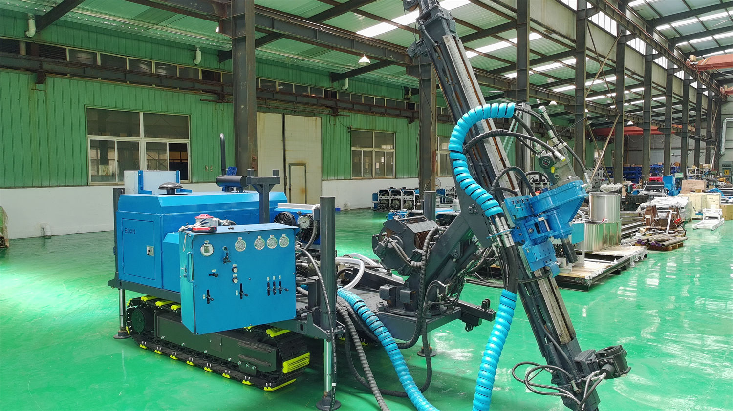
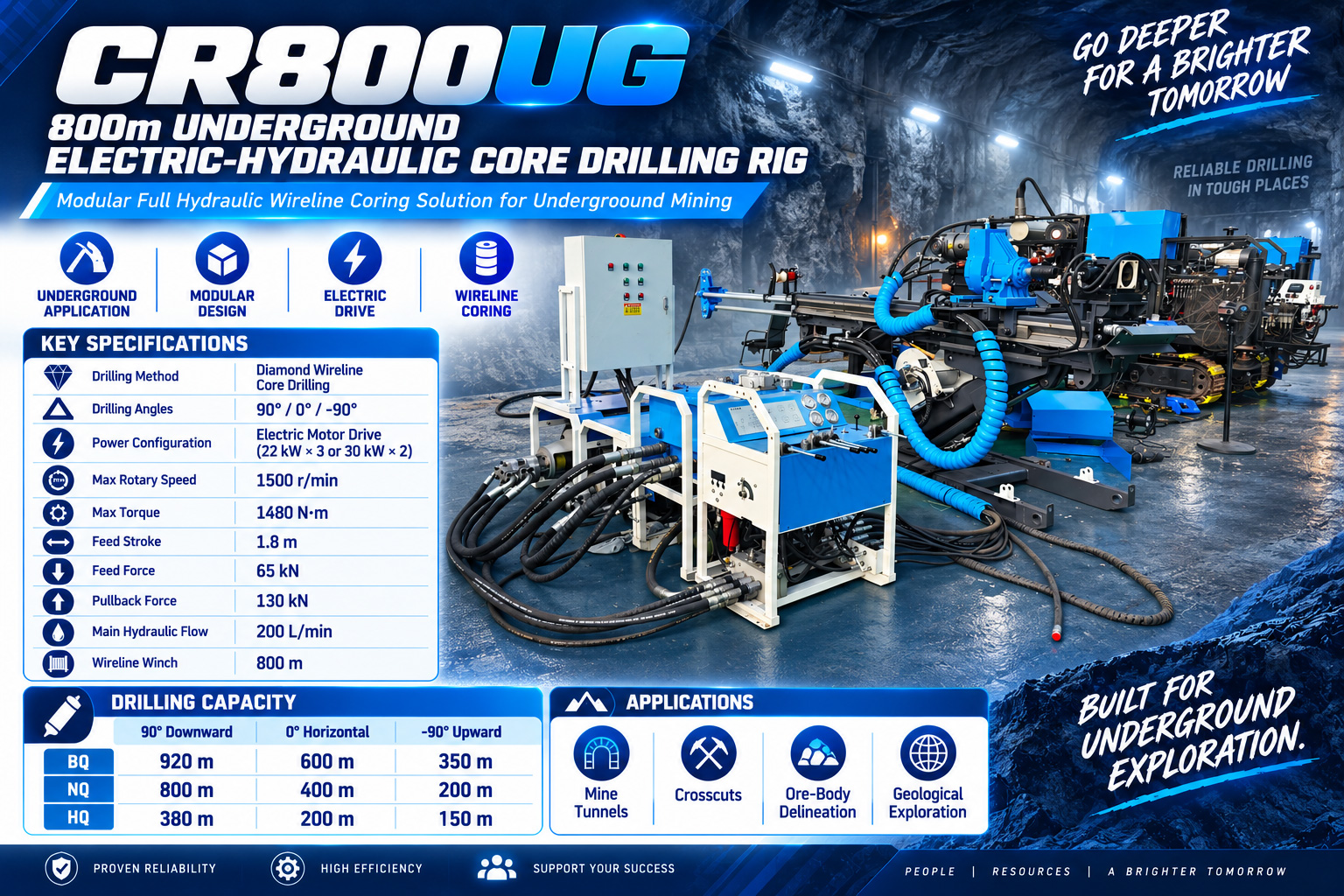
On the power side, the CR800UG uses electric motor power, configured as 22 kW × 3 or 30 kW × 2, with main system flow 200 L/min, pressure 210 bar, and auxiliary pump flow 10 L/min, maximum pressure 150 bar. The electric motor solution produces no combustion exhaust at the drill site, making it more suitable for underground mines with a stable power supply system. During actual configuration, the electrical scheme should be confirmed based on mine voltage, frequency, cable length, and starting method.
There is a boundary easily confused with drilling parameters: standard motor configurations cannot be directly regarded as explosion-proof configurations. In coal mines, gassy mines, or underground environments with combustible dust, the corresponding explosion-proof grade motors, control boxes, cables, and protection systems should be confirmed according to local mine safety regulations.
Layer 3: Hole Direction and Angle Definition
Once the direction is set, the reference coring capacity of the same equipment has a corresponding value. The CR800UG data provides reference drilling depths for BQ / NQ / HQ under three reference conditions:
| Reference Condition | BQ | NQ | HQ |
|---|---|---|---|
| 90° | 920 m | 800 m | 380 m |
| 0° | 600 m | 400 m | 200 m |
| -90° | 350 m | 200 m | 150 m |
The data explains the uses of the three directions: the 90° direction is suitable for verifying orebody extension from the current mining level to deeper levels; horizontal holes can directly control orebody thickness, surrounding rock boundaries, and mineralization continuity from crosscuts or haulage drifts; upward holes can be used to verify mineralization above the drift, roof structures, or upper resources in the mining area.
Special attention should be paid to the notation of positive and negative angles. Different mines may define positive and negative angles differently. Before formal construction, the on-site installation direction and design drawings should be used as the standard.
Layer 4: Drill String Configuration and Collar Operations
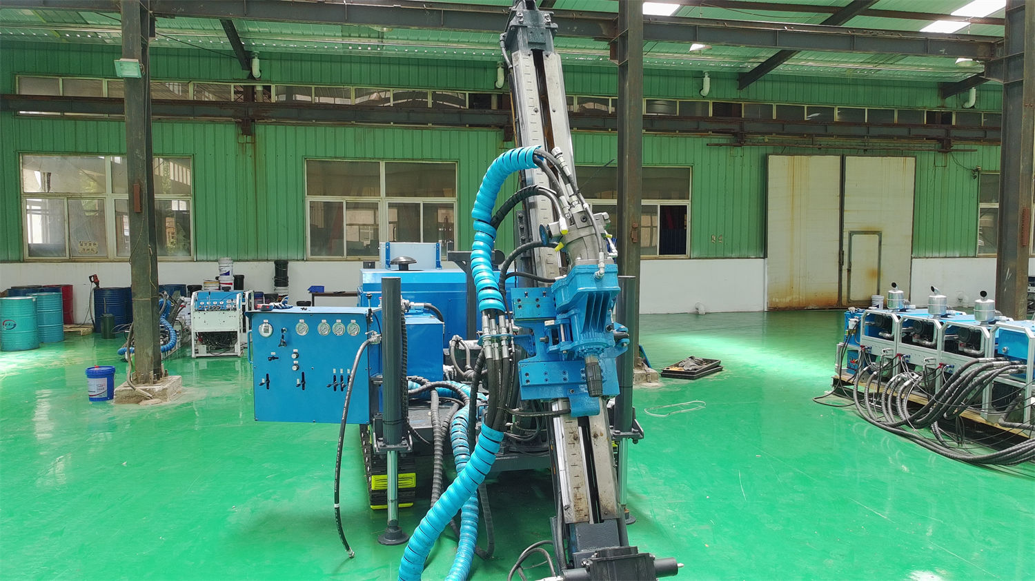
The values at the drill string layer determine whether in-hole operations can be continuous. The CR800UG power head is a hydraulic top drive with a rotation speed of 0–1500 rpm, torque range 600–1480 N·m, equipped with a 107 variable motor; the feed mechanism is hydraulically cylinder-driven with a stroke of 1800 mm, thrust force 65 kN, pull force 130 kN, and rapid traverse speed 0.9 m/s.
Collar operations are concentrated here: the drill rod holder has a maximum applicable drill rod size of 108 mm, through-hole 128 mm, and clamping force 80 kN. Underground drill site space is limited, and drill rod make-up/break-out and collar operations are concentrated. Stable clamping can reduce the risk of drill rod slippage; during construction, the wear of clamping blocks and hydraulic pressure should be checked regularly.
Feed and pullback parameters are not fixed values. The stress states of the drill string in horizontal, downward, and upward holes are different and should be adjusted according to hole direction, hole depth, and friction changes.
Layer 5: Coring Method and Hoisting System
On the coring side, the data states that wireline coring is used. The hoisting system has a rope capacity of 800 m, using 6 mm wire rope; the data lists a minimum lifting force of 800 N for a full tube and a maximum lifting force of 1800 N for an empty tube, with lifting speeds from 1.8 m/s to 4.8 m/s. Wireline coring can reduce repeated tripping of the entire drill string, helping to reduce auxiliary time in underground medium-deep hole construction.
For flushing and special circulation, the equipment can be optionally equipped with a 120 series high-pressure plunger pump, with a maximum flow of 120 L/min and maximum pressure of 70 bar.
Hydraulic oil temperature control requires separate arrangements in underground environments: the hydraulic oil tank capacity is 100 L and uses water cooling; underground air flow conditions are limited, and water cooling helps control oil temperature, but cooling water supply and heat exchanger flow must be ensured. When water quality is poor, the heat exchanger should be cleaned regularly.
Layer 6: Reverse Modification of Procedures by Formation Conditions
Even after the first five layers are established, the formation can still rewrite two things. When encountering fault gouge, breccia, or strongly fractured zones, the data suggests shortening runs, reducing thrust, and observing changes in return water; if necessary, use casing, adjust flushing fluid, or perform staged treatment. The focus in such formations is maintaining borehole wall stability and improving effective core recovery, rather than simply pursuing footage.
Water-bearing structures fall under the advanced geological drilling stage. Through drill core, return water, and pump pressure changes, the degree of fracture development and water-bearing structures can be assessed. For areas with possible water inrush, surrounding rock instability, or abrupt lithology changes, obtaining core information in advance can provide a basis for support, drainage, and pre-grouting plans. When constructing upward and horizontal holes, special precautions should be taken against safety risks from drill rods, core barrels, and high-pressure fluids.
Items to Confirm with the Manufacturer
- There are two different specifications for the operating unit weight in the original parameters: 130 kg in the operating unit table and 90 kg in the main module weight summary. Both specifications are retained in this article's parameters. The final supply configuration and actual weight should be based on formal technical confirmation documents.
- The angle definitions for the 90°, 0°, and -90° directions need to be verified one by one against the on-site installation direction and design drawings.
- The electrical scheme corresponding to mine voltage, frequency, cable length, and starting method, as well as whether explosion-proof requirements exist, must be confirmed for the specific mine.
Due to differences in actual geological conditions, in-hole tools, drilling angles, and operating methods, the final drilling efficiency, drilling depth, and core recovery results should be based on on-site conditions.