












In the CR800I product materials, the drilling depth specification section is usually written as three rows: HTW reference drilling depth 500 m, NTW reference drilling depth 800 m, and BTW reference drilling depth 1000 m. In the model parameters on this site, there is another notation: BQ 1000 / NQ 800 / HQ 500, with coreBqM 1000, coreNqM 800, and coreHqM 500 listed simultaneously. These two notations point to the same range of drilling capability, just under different labeling systems. The order in which to read this table depends on which question needs to be answered first.
First confirm that the two specification notations refer to the same line
HTW, NTW, and BTW belong to one specification code sequence, while BQ, NQ, and HQ belong to another. In the known materials for this article, both groups correspond to the meaning of "reference drilling depth," and the three fields coreBqM 1000, coreNqM 800, and coreHqM 500 in the model parameters on this site correspond one-to-one with the values HTW 500, NTW 800, and BTW 1000. The materials do not elaborate on the conversion details between the two code sets, nor do they state whether they fully overlap in all diameter values. Therefore, what can be confirmed is the numerical pairing relationship; one cannot independently infer the maximum core diameter, borehole diameter, or drill rod outer diameter corresponding to each specification—these do not appear in the existing materials.
If the procurement documents or design tasks use the BQ / NQ / HQ notation, when reading the table simply match them to the three fields coreBqM, coreNqM, and coreHqM; there is no need to first convert the codes.
Why the three specifications cannot be compared horizontally by size
The most easily misread point is to sort the three numbers 500, 800, and 1000 by size, and then treat the middle row as the standard capability of this equipment. These three numbers are not three levels of the same thing at different depths, but rather the reference depths achievable by three different borehole specifications.
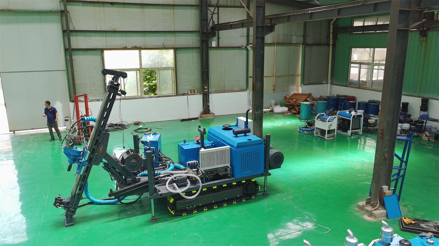
| Specification | Reference Drilling Depth | Direction of Increasing Specification Size |
|---|---|---|
| HTW | 500 m | — |
| NTW | 800 m | — |
| BTW | 1000 m | — |
The "Direction of Increasing Specification Size" column in the table lacks a basis in the existing materials, so it is left blank. What can be confirmed are the three row values themselves. The larger the borehole specification, the shorter the drill string length that the same equipment can typically safely push and lift, so the materials place 500 m in the HTW row and 1000 m in the BTW row. Reading it in reverse—thinking that 500 m is the upper limit of this equipment and 1000 m is its strength—would misunderstand both ends at the same time.
This is also where the 800 m in the model name easily causes disagreement. According to the materials, 800 m corresponds to the NTW row, not the maximum or minimum of the three rows. Understanding it as "the reference drilling depth of this equipment under the NTW specification" is closer to the original meaning of the materials than understanding it as "the equipment's maximum drilling depth."
Decide which row to read first based on project objectives
The row order of the drilling depth specification table is fixed, but the order in which to read it should be determined by project objectives, not by reading from top to bottom.
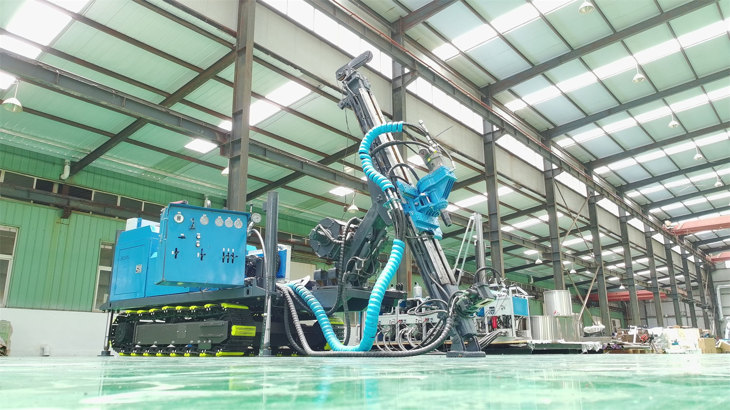
- When the core specification has already been determined, start from the row where the target specification is located, confirm whether the reference drilling depth covers the design hole depth, and then look back at the other two rows as adjustment space.
- When the hole depth is fixed and the core specification is yet to be determined, work backward from the row covering that hole depth to find the specification, then check whether the core size corresponding to that specification meets logging and assay requirements.
- When only conducting supplementary exploration or shallow-hole reconnaissance in a mining area, there is no need to read downward from the 1000 m row; simply leave unused rows unused.
Regarding the relationship between specifications and core sizes mentioned here, the materials only provide codes and do not give specific diameter values. In actual projects, it is necessary to confirm with the manufacturer the borehole diameter and core diameter corresponding to each specification.
The premises for the validity of these three row values are written elsewhere in the materials
All three drilling depth rows are preceded by the word "reference." Other conditions related to the drilling process in the CR800I materials are scattered across different paragraphs and need to be kept in mind when reading the table:
- Drilling angle 45°–90°; inclined holes and near-vertical holes both affect the stress state of the drill string in the hole, yet the table does not provide drilling depths segmented by angle.
- Power head speed 0–1500 rpm, high-speed gear torque approximately 300–800 N·m, torque gear approximately 300–1000 N·m; high-speed gear transmission ratio 1:2.2, low-speed gear 1:3.
- 152 kN pull-up force and 63 kN feed force, corresponding to tripping, drill tool handling, and the increased drill string self-weight and borehole wall friction in deep hole sections.
- The winch uses 6 mm wire rope, with a rope capacity of 1000 m, lifting force 13 kN, and lifting speed 120 m/min; this set of values is interrelated with the hole depth for wireline coring.
- Hydraulic mud pump reference flow 100 L/min, pressure 70 bar, providing circulation conditions for drill bit cooling, cuttings carrying, and borehole wall stability.
- The power system is standard with a Cummins engine, and a domestic engine can also be selected according to configuration; rated power 132 hp (97 kW), rated speed 2200 rpm, turbocharged with air-to-air intercooling.
The main pump is an A11 series variable displacement piston pump, with a maximum pressure of 30 MPa; the auxiliary pump is an A10 series variable displacement piston pump, with a maximum pressure of 20 MPa. These values describe the equipment-side power supply and execution conditions, but the materials do not give the corresponding relationship of "how many meters NTW can stably drill in a certain formation at a certain angle."
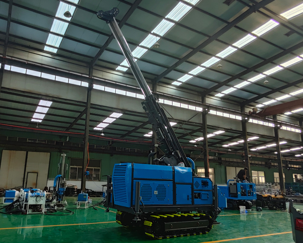
What the materials do not answer
The drilling depth specification table itself is a reference value, and what it does not state includes:
- The specific core diameter and borehole diameter values corresponding to each specification;
- Whether the reference drilling depth is adjusted under different drilling angles;
- How different lithologies and borehole wall stability affect the reference drilling depth;
- Under what drill tool combinations and process conditions the three row values were obtained.
Therefore, this table is suitable for judging "whether the project target specification falls within the capability range of this equipment," but not for directly serving as a hole completion commitment. Actual drilling depth, coring performance, and efficiency must also be judged in combination with formation conditions, downhole tools, drilling angle, and operating methods, and the final reference should be based on on-site working conditions and equipment technical confirmation materials.