












“With a sampling system installed, samples will not cross-contaminate”—this conflates two things: first, the three-in-one system reduces manual sample pouring and secondary transfer; second, whether cuttings from adjacent depth intervals are actually not mixed together. The RC600-CS3 information is clear on the former: after cuttings return to the surface through the inner tube of the dual-wall drill pipe, they directly enter the cyclone system for gas-solid separation, then enter the splitting and bagging stage, reducing manual sample pouring and secondary transfer. This describes how samples are connected along the return path. Cross-contamination risk mainly occurs at the cleaning nodes between path segments and in the depth recording stage, and these two segments are not within the system’s scope of responsibility.
First, answer the core question: which segment does this system change?
According to the RC600-CS3 information, the three-in-one sampling system consists of three stages: cuttings return, cyclone separation and representative splitting, and sample collection. The system operates continuously: cuttings enter the cyclone system for gas-solid separation, then enter splitting and bagging. Compared with manually pouring samples at each stage, the continuous path reduces the number of times samples are transferred between containers. Fewer transfers also reduces the chance of cuttings being exposed to residual material in containers from the previous depth interval. This is a favorable condition for preventing cross-contamination, but it is only a structural advantage, not a guarantee of the result. The information also states that each sample bag should be marked with the drill hole number, sample number, start and end depths, date, and shift, and that field records should be consistent with the sample bags. It can be seen that the depth correspondence still has to be established through marking and records; the system itself does not generate depth information.
Continuity of the return path is not proof of depth isolation
Reverse circulation drilling obtains cuttings samples, not complete cores. Cuttings travel upward from the hole bottom along the inner tube of the dual-wall drill pipe and are continuous inside the hole; after entering the cyclone system, they are bagged in time-based segments. The segmentation is based on the sampling interval set on site. The example given in the information is collecting one bag every 1 m or every 2 m, while simultaneously recording the drill hole number, start and end depths, and sample number. In other words, “which bag corresponds to which hole depth interval” is determined by the correspondence between the sampling interval and the records, not by the cyclone itself. The information does not provide a mechanism for automatic depth-based segmentation inside the cyclone system, so one cannot infer from “continuous sample return” that “each depth interval is automatically isolated.”
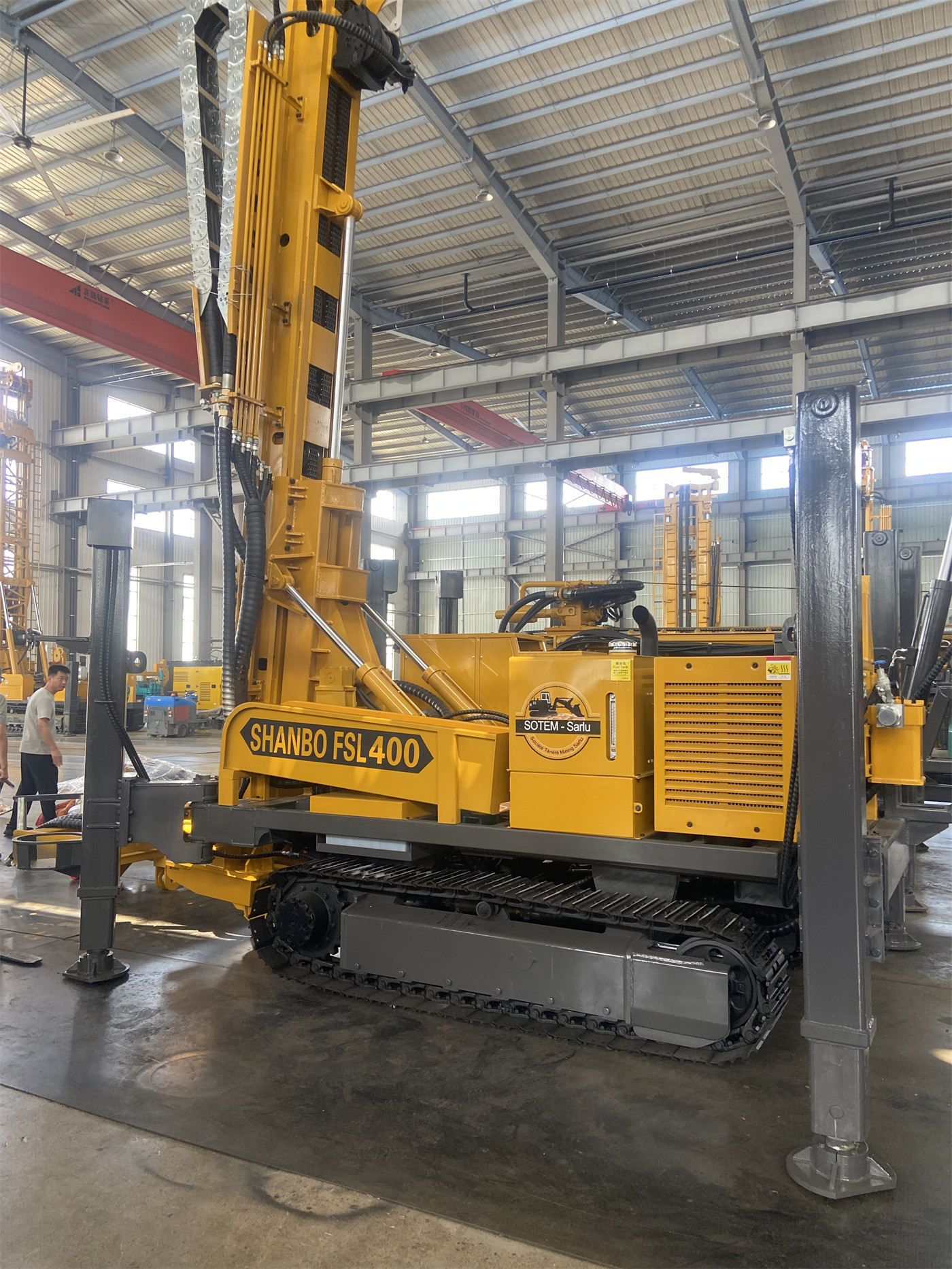
Cleaning nodes specified in the information
The three-in-one system information explicitly states cleaning requirements in two places, and these are the most direct on-site actions for preventing cross-contamination:
- Inside the cyclone, splitter, and sample return hose: each time drilling stops, the hole is changed, or a new key sampling interval is entered, check whether residual cuttings from the previous interval are present, to avoid mixing samples from the previous depth into the next sampling interval.
- Dual-wall drill pipe seals: included in the daily pre-start inspection items. In deep holes, drill pipe seals affect the continuity of sample return, and abnormal seal conditions will change the return rhythm.
The information also mentions that the sample return hose should be checked before daily start-up, and whether sample return is continuous should be continuously observed during construction. The relationship between these two actions and cross-contamination risk is indirect: discontinuous sample return can cause cuttings to remain in the hole and then return in a concentrated burst, worsening the correspondence between samples and actual depths. This point is listed separately under conditions of fractured zones and air-leakage formations.
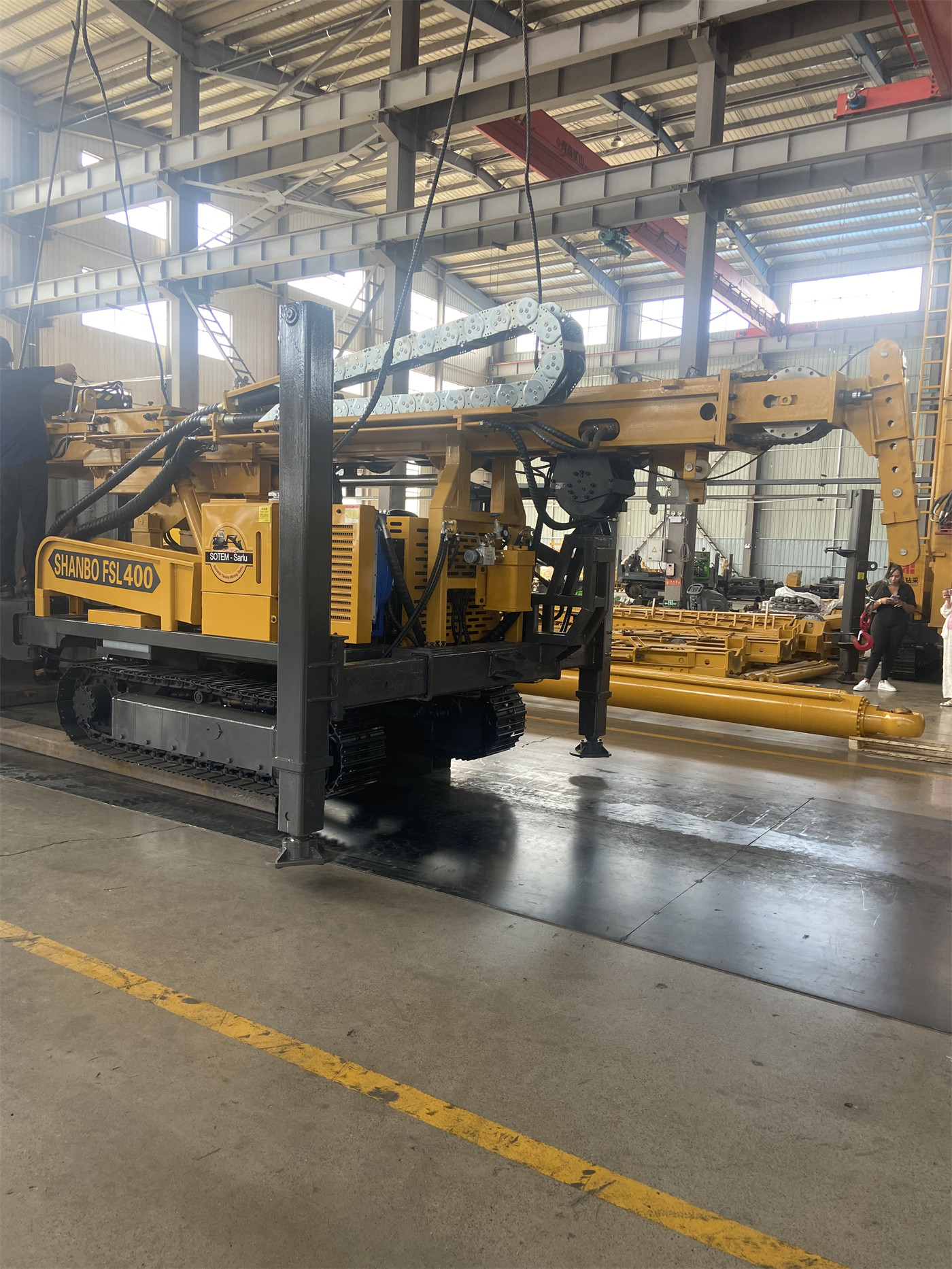
Three types of interference conditions that are easily overlooked
| Condition | Relevant description in the information | Direction of impact on depth correspondence |
|---|---|---|
| Fractured zones and large fissures | Air leakage may cause cuttings to remain in the hole and then return in a concentrated burst | Worsens the correspondence between samples and actual depths |
| Drilling stop, hole change, entering a key sampling interval | The cyclone, splitter, and sample return hose may retain cuttings | Residue from the previous interval may mix into the next interval |
| Insufficient air volume | May manifest as reduced sample return, delayed sample return, and bottom-hole cuttings accumulation | Delayed sample return changes the depth basis for segmented bagging |
The common point of these three conditions is that none of them changes the system structure, but all of them change the moment when cuttings actually reach the cyclone. Bagging is based on the arrival time, not the drilling time at the hole bottom, and there is a time difference between the two caused by the sample return travel. The information recommends an air consumption of 16–75 m³/min and a working pressure of 1.6–6 MPa; one of their purposes is to allow cuttings to continuously return to the cyclone system through the inner tube. As hole depth increases, the effects of air volume loss, drill pipe sealing, and in-hole air leakage on sample recovery become more pronounced.
Preventing cross-contamination also depends on the sample marking system
The sample management elements given in the information include: drill hole number, sample number, start and end depths, date, and shift, with records required to be consistent with sample bags; if the project implements a QA/QC system, duplicate samples, standard samples, and blank samples should also be set up as required. These contents are written alongside the three-in-one system in the information, rather than as functions of the system. It can be understood as follows: the system addresses how samples reach the surface and how they are split and bagged, while numbering and depth records address whether samples can be traced. If there is only continuous sample return without corresponding numbering records, the correspondence between sample bags and depths cannot be reconstructed during post-processing.
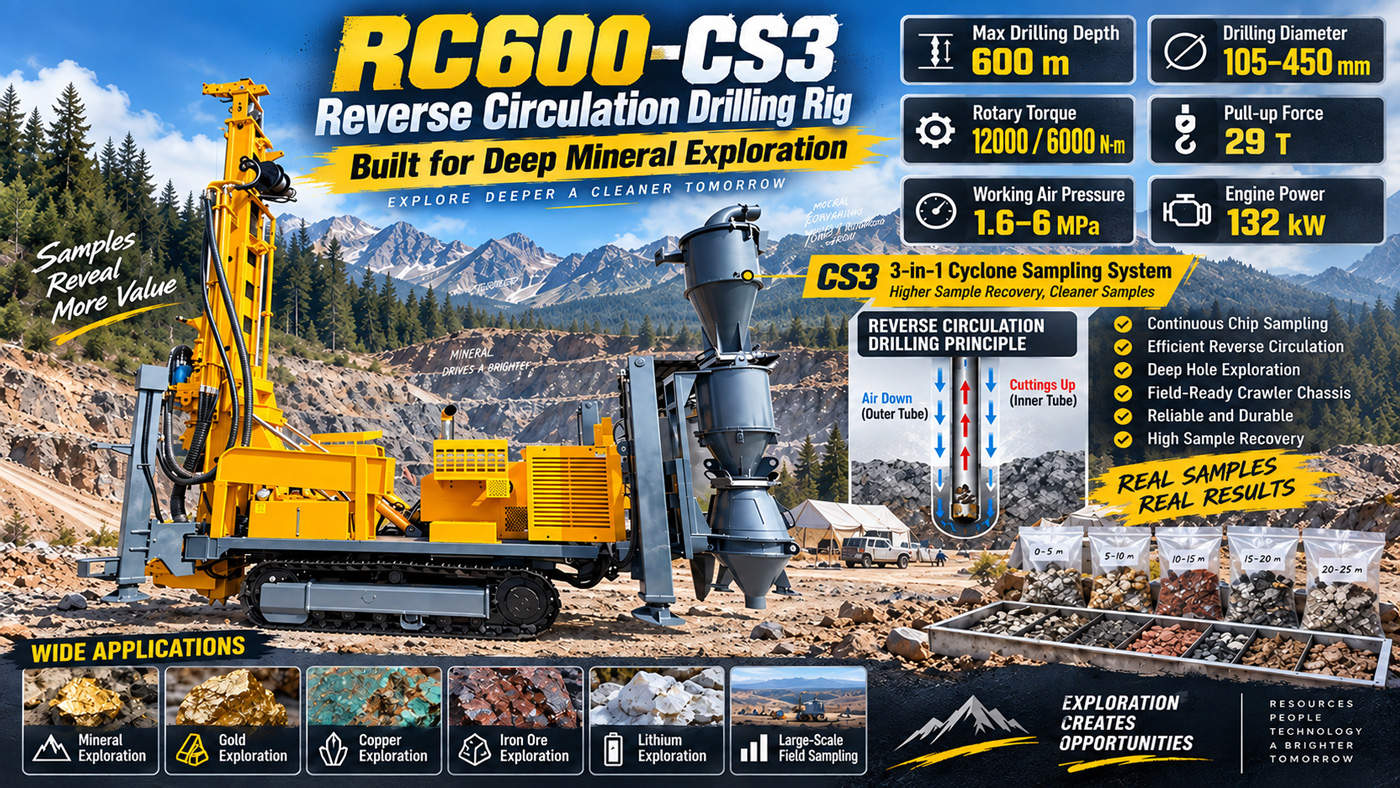
Which questions this information does not answer
- The cleaning frequency, cleaning method, and time required per cleaning for the cyclone and splitter; the information only gives principled statements such as “should be checked” and “clean promptly.”
- The maximum allowable residual amount between adjacent sampling intervals; the information does not provide quantitative indicators.
- The actual delay time for sample return from the hole bottom to the cyclone, and its conversion relationship with hole depth, air volume, and drill string assembly.
- The range of representativeness deviation in the splitting stage (for example, the splitter’s distribution ratio for cuttings of a specific particle size); the information does not cover this.
These items involve specific project execution standards and on-site conditions, and need to be confirmed with the manufacturer or the project technical lead; generic values should not be used as substitutes. In preventing cross-contamination, the three-in-one sampling system provides a shorter material path and fewer transfer stages; sample isolation between depth intervals is still maintained jointly by three lines: cleaning actions, sample return continuity, and depth records.