












Writing "500-meter-class water well project" in the equipment column usually leaves only one line: maximum drilling depth 500 m. But the same requirement specification often also includes well diameter range, casing size, submersible pump specifications, aquifer burial depth, site access method, and who supplies the air compressor. These items do not automatically become equipment conditions; they need to be broken down one by one to match specific parameters. Below, using the values published for the RC500E on this site as a reference, the requirements of a 500-meter-class water well project are broken down into several categories of verifiable capability conditions.
First break down the target depth: which segment does 500 m represent on this rig
The maximum drilling depth listed in the RC500E documentation is 500 m, with a hole diameter range of 140–400 mm. These two values are tiered conditions, not every well needs to use both at full capacity. In actual projects, well depth is determined by hydrogeological data and the location of the water-producing layer, while well diameter is determined by the casing, screen, and submersible pump dimensions. Treating both upper limits as target values simultaneously will overestimate the equipment load and cause the matching air compressor and drilling tool configuration to deviate as well.
A more practical approach is to first fix two known quantities: completed well depth and design well diameter. Once these two values are determined, the drill pipe length to be handled in the hole, the drill string weight, and the annular cuttings removal volume have a basis for comparison. The remaining conditions then revolve around these two figures.
Which stage of the operation does hoisting force constrain
The RC500E has a hoisting force of 300 kN and a feed force of 150 kN. In 500-meter-class boreholes, the self-weight of the drill pipe, borehole wall friction, and casing weight all accumulate with depth. Hoisting force here constrains tripping, casing running, and recovery of downhole tools, rather than directly determining penetration rate.
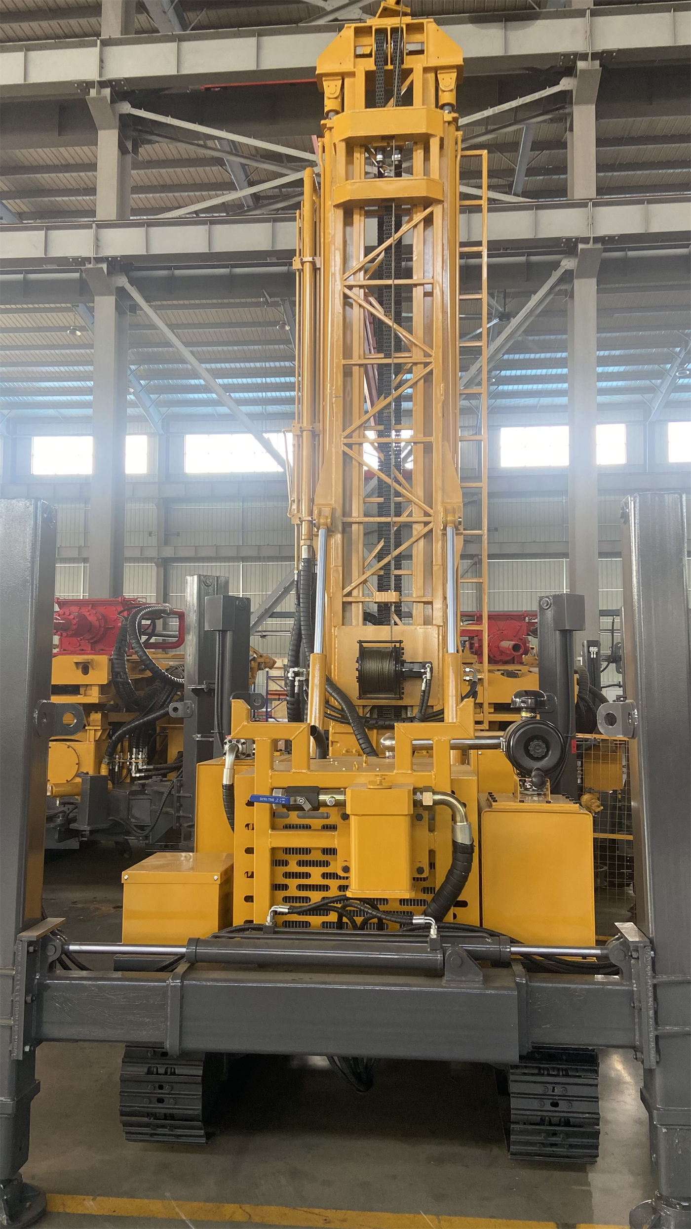
It is important to distinguish: having a numerical margin in hoisting force does not mean that maximum hoisting force can be used to pull forcefully when abnormal resistance is encountered. The guidance in the documentation for handling abnormal downhole resistance is to first clean the hole, assess the situation of falling blocks and settled cuttings in the hole, and then decide on the handling method. Hoisting force provides an operating margin in such situations, not a solution to the problem.
Rotary torque and rotation speed must be considered as a pair
This rig has a rotary torque of 8000–12000 N·m and a rotation speed of 40–160 r/min, using variable frequency speed control. The combination of large diameter, hard rock, and high friction is better suited to low speed and high torque; stable hole sections with lower downhole resistance can use higher rotation speeds. These are two directions of the same hydraulic rotary system, and the torque value alone cannot determine which setting should be used for a given formation.
The applicable rock formations listed in the documentation include granite, basalt, limestone, and sandstone, and it states that such relatively intact rock formations use DTH down-the-hole drilling. During hard rock construction, the DTH hammer impact, rotation speed, feed force, and air volume need to be coordinated and matched. If cuttings removal at the hole bottom is poor, continuing to increase feed may instead aggravate bit wear and increase the risk of sticking.
Air-lift reverse circulation changes the cuttings removal path and also introduces a hard supporting requirement
The RC500E uses an air-lift reverse circulation process. Compressed air establishes reverse flow in the inner pipe, carrying rock cuttings and drilling debris from the hole bottom back to the surface along the inside of the drill pipe, rather than traveling a long distance up the annulus. For deep hard rock water wells, this path helps keep the hole bottom clean and reduces repeated crushing of cuttings and settled debris problems. However, the documentation also states that the actual effect depends on air compressor displacement, hole diameter, drill pipe sealing, and formation conditions.
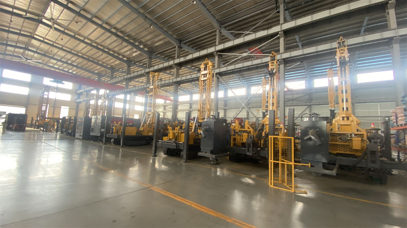
Therefore, air-lift reverse circulation is not only reflected in the drilling rig; it transfers a hard requirement to the supporting system: the air compressor. The recommended working air pressure given in the documentation is 1.7–3.5 MPa, with air consumption of 17–42 m³/min. As hole depth increases, hole diameter increases, rock formation hardens, or construction altitude rises, the required displacement increases. When selecting the configuration, the air demand of both the DTH hammer and reverse circulation cuttings return must be considered simultaneously.
| Capability condition | RC500E published value | Constrained operation |
|---|---|---|
| Drilling depth and hole diameter | 500 m; 140–400 mm | Completed well depth and well diameter design |
| Hoisting force and feed force | 300 kN; 150 kN | Tripping, casing running, tool recovery |
| Rotary torque and rotation speed | 8000–12000 N·m; 40–160 r/min | Rotary load under hard rock and large diameter conditions |
| Working air pressure and air consumption | 1.7–3.5 MPa; 17–42 m³/min | Air-lift reverse circulation cuttings return and DTH hammer air supply |
| Power | 132 kW diesel, 2400 r/min | Independent operation at sites without stable power supply |
Formation conditions split the same set of parameters into different requirements
The documentation explains precautions for several types of formations: faults and fractured zones are prone to falling blocks, hole shrinkage, air leakage, and sticking; after entering such hole sections, feed speed should be reduced, continuous hole cleaning should be maintained, and casing or foam assistance should be used according to borehole wall stability; the difficulty in weathered rock and upper loose overburden is unstable borehole walls, and casing, mud, or other hole stabilization methods can first be used to establish a stable hole section before entering relatively intact rock for pneumatic reverse circulation; after entering the main aquifer, groundwater will change the cuttings return and DTH hammer working state in the hole, and the depth of the main water-producing layer should be recorded, with air supply, hole cleaning, and casing methods adjusted accordingly.
Open fractures, karst caves, and high-permeability formations may experience severe air leakage. The documentation states that if only pressure is increased while displacement is insufficient, effective airflow may still not be obtained at the hole bottom; depending on the degree, air compressor displacement can be increased, foam can be used, casing can be used, or the drilling method can be adjusted. These situations all point to one thing: in the equipment conditions of a 500-meter-class project, the relationship between formation judgment and air compressor displacement is more direct than the drilling depth figure itself.
Feed stroke and drill pipe specifications affect construction organization
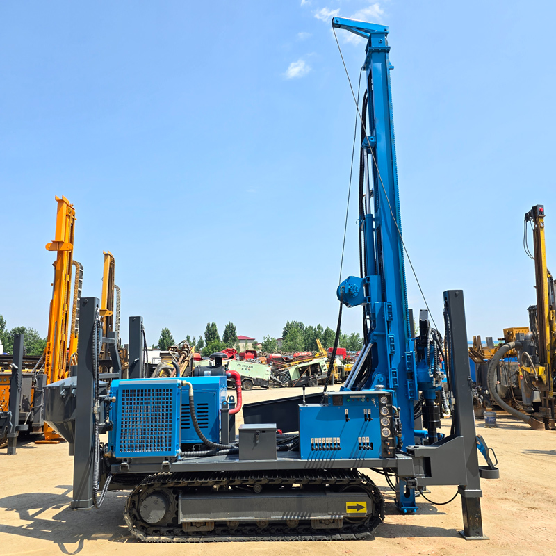
The RC500E can be configured with a 3.3 m or 6.6 m feed stroke and supports 1.5 / 2 / 3 / 6 m drill pipes. The 6.6 m long stroke is suitable for projects that want to reduce the number of pipe connections and improve continuous drilling efficiency; the 3.3 m configuration is more conducive to controlling the overall working height and site adaptability. This choice not only affects efficiency but also affects the transport plan and hole position space arrangement.
Transport dimensions are approximately 6300 × 2100 × 2500 mm, working dimensions are approximately 4000 × 2900 × 6800 mm, and the overall weight is approximately 12 T. Before relocation, vehicle load capacity, loading fixation points, and road height limits need to be confirmed; after arrival, space for raising the mast and a safe working area must also be reserved. Crawler travel speed is approximately 2.5 km/h, with a reference gradeability of 30°, making it more suitable for gravel roads in mining areas, rural roads, and generally uneven ground; movement in soft soil and wet slippery areas should be cautious.
Beyond these conditions, items that still need separate confirmation in the project
- The final depth of the well position and the location of the water-producing layer must be based on hydrogeological data and actual drilling conditions; the equipment drilling depth does not constitute a guarantee of water production.
- Who supplies the air compressor and whether the site has a stable power supply will directly affect the power scheme and supporting costs.
- For dewatering well projects, the hole position, well diameter, screen, pump capacity, and spacing need to be determined based on hydrogeological calculations; the equipment only performs the drilling operation.
- The complete construction system can be optionally configured according to the project with reverse circulation DTH hammers, bits, drill pipes of different specifications, casing tools, air compressors, high-pressure air hoses, oil mist lubricators, foam pumps, and generators, etc.; not all configurations are needed for different formations.
After breaking down a 500-meter-class water well project into the above categories of conditions, it becomes clearer that drilling depth is only the entry point. Hoisting force, rotary torque, the cuttings removal path of air-lift reverse circulation and the matching air pressure and displacement, feed stroke, and relocation conditions each constrain different operations, and they need to be checked together to truly match the requirements to the equipment.