












How many piles are driven in a shift in a photovoltaic field rarely depends only on how fast drilling is. Pile positions are arranged according to array rules. Between each pile point, the equipment must perform movements including turning, alignment, posture adjustment, drilling, and repositioning—a considerable portion of which is unrelated to drilling itself. Only by counting these movements can one determine where the actual rhythm difference of a machine lies on dense pile positions. Using the published specifications of the PV390R as a reference, this article breaks down whole-machine movements during continuous pile layout into several stages.
Time consumption in continuous pile layout falls first between pile points, not within holes
Pile positions in ground-mounted centralized photovoltaic power stations are usually arranged in rows and columns at fixed spacing. The number of pile positions within a construction face is large, single-hole depth is 0–6 m, and hole diameter is within 80–600 mm according to foundation design. The time for drilling a single hole itself is relatively limited, but after completing each pile point, the equipment must handle where the next pile is located, whether the mast needs a different angle, and whether the chassis needs to move forward. The denser the pile positions and the smaller the row spacing, the higher the proportion of these non-drilling movements in a shift.
If every pile point relies on the chassis repositioning for hole alignment, walking, leveling, and re-adjusting posture will occur repeatedly. The idea of reducing movements is not to make the equipment walk faster, but to allow one stopped position to cover pile points in more directions.
Orientation adjustment: 360° rotation replaces whole-machine turning
The upper working mechanism of the PV390R can rotate 360° around the chassis. For continuous pile layout, the function of this stage is that after the chassis is stabilized, the drilling direction can be redirected over a wide range without walking and turning the whole machine to a new orientation.
- When multiple pile points in different directions need to be handled from the same stopped position, rotation handles orientation switching;
- When the construction face is narrow and there is insufficient room for the whole machine to turn, rotation reduces large repositioning movements;
- When pile positions are dense, rotation works with the subsequent swing arm and telescopic compensation to complete hole alignment.
It should be distinguished that 360° rotation reduces whole-machine orientation adjustment, which does not mean the chassis does not need to move. When pile spacing exceeds the compensation range, repositioning will still occur.
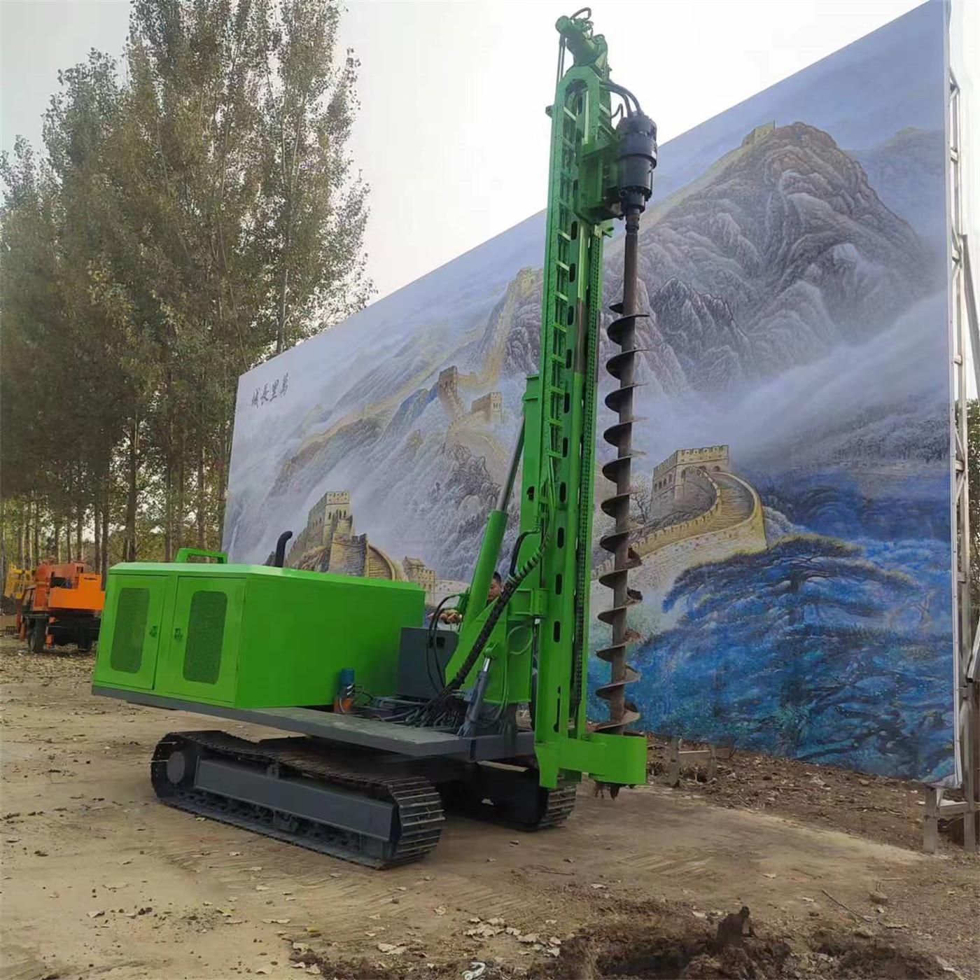
Posture adjustment: 120° mast pitch corresponds to site elevation differences
The problem in mountainous photovoltaic and uneven sites is that after the equipment is stabilized, there is often a deviation between the working posture and the designed angle of the pile position. The PV390R's mast pitch range is 120°, allowing drilling posture to be adjusted while the chassis posture remains fixed.
The movement replaced at this stage is repeatedly moving the chassis position to find an angle that can align. Slope, terrain undulation, and pile position arrangement all affect the range of angles that need adjustment. The actual usable range should be considered together with the flatness of the stopped platform. The materials do not provide working efficiency data under different slopes and stratum conditions, so no quantitative conclusion is made on how many movements can be reduced at a specific site.
Lateral correction: dual-cylinder swing arm leaves fine hole alignment to the mast
After orientation and posture are roughly in place, the remaining deviation is usually lateral. The PV390R uses a dual-cylinder left-right swing arm, which can make lateral corrections to the drilling position while the chassis is already stabilized.
Separating lateral correction from chassis movement is a relatively practical stage in continuous pile layout. The reason is that lateral fine adjustment of the chassis often requires walking coordination, involves large movements, and is not easy to achieve in one attempt; the swing arm is a small-range mechanism movement, more direct for array layouts with smaller pile spacing.
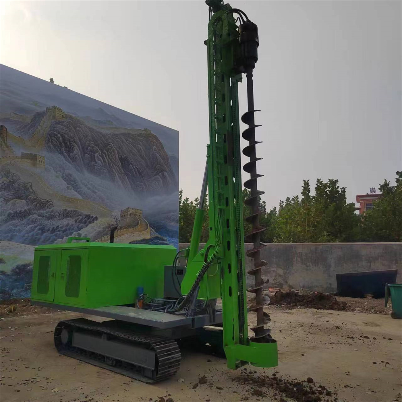
Front-rear positioning: the range covered by 500 mm telescopic compensation
The PV390R provides 500 mm telescopic compensation for fine adjustment of pile positions in the front-rear direction. The four compensation methods combined are: 360° rotation for orientation, 120° mast pitch for posture, dual-cylinder swing arm for lateral correction, and 500 mm telescopic compensation for front-rear positioning.
Each of these four stages has its own range. Telescopic compensation of 500 mm means that front-rear deviations beyond this distance still need to be resolved by moving the crawler chassis. If pile spacing is significantly greater than the compensation amount, the room for saving movements through compensation will narrow. The materials do not provide measured productivity data under continuous pile layout conditions, so the specific number of repositioning movements saved cannot be calculated from this.
| Movement stage | Corresponding mechanism | Published value | What is reduced |
|---|---|---|---|
| Orientation adjustment | Upper 360° rotation | 360° | Whole-machine turning and large steering |
| Posture adjustment | Mast pitch | 120° | Repeated repositioning to find an angle |
| Lateral correction | Dual-cylinder left-right swing arm | Swing angle value not provided in materials | Small-range lateral chassis movement |
| Front-rear positioning | Telescopic compensation | 500 mm | Front-rear deviation within 500 mm |
Chassis movement is not eliminated, only compressed to which stage
Dense pile positions do not mean the chassis can remain stationary. The crawler chassis is still responsible for site transfer and displacement beyond the coverage of one stopped position. Track shoe width is 400 mm, climbing angle is 35°, suitable for dirt roads, grassland, gravel ground, and general unpaved construction surfaces.
The premise for compressing movement to fewer times is that the coverage of a single stopped position is large enough. This range is determined jointly by rotation angle, swing arm stroke, and telescopic compensation amount. Among these, the swing angle of the swing arm is not provided in the materials, and telescopic compensation is 500 mm. This part needs to be calculated specifically in conjunction with the pile position layout drawing.
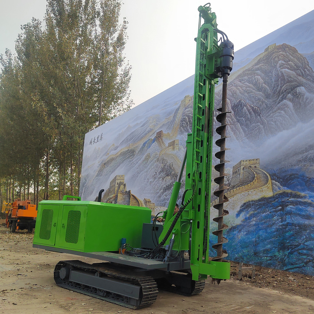
Power and pressurization method affect the stability of continuous operation
The PV390R is equipped with an 85 kW Yuchai four-cylinder engine, reducer torque of 13000 N·m, drill rod speed of 90 r/min, and adopts chain pressurization. These parameters determine whether the in-hole stage can advance stably and the construction capability within the range of 80–600 mm hole diameter and 0–6 m hole depth.
The requirements of continuous pile layout on the power system are reflected in long-term repeated starting and stopping and posture adjustment. Maintenance of cooling, air filtration, and fuel systems is routine. This part does not change the number of movements between pile points, but it affects how many piles can be continuously completed within one shift.
Reducing movements does not mean it is universal for any site
The four compensation methods act on hole alignment movements and do not change other boundaries of the equipment:
- Drilling diameter 80–600 mm, depth 0–6 m, belonging to the range of shallow foundation pre-drilling and guide hole drilling;
- This equipment is not a water well drilling rig; it is positioned as photovoltaic and engineering pile driving and drilling equipment;
- After replacing with impact drilling tools, it can be used for strongly weathered rock and rock layers, but the materials do not provide impact hammer model and impact energy, so hard rock efficiency is not inferred;
- In heterogeneous strata such as pebble sand and backfill layers, advancement speed is still controlled by rotary load and slag discharge status;
- During upper rotation operation, confirm that there are no people, vehicles, overhead lines, or other mechanical interference around, and personnel must not enter the rotation drill rod, chain pressurization mechanism, mast swing, and upper rotation range.
There are differences in pile type, stratum, hole diameter, construction angle, and operation method. The final hole quality and pile driving effect should be based on on-site working conditions and project foundation design.