












"600-meter-class" sounds like a target value that can be directly matched: the requirement says 600 meters, the equipment documentation says 600 meters, and it appears to be a match. But in water supply projects, what needs to be determined first is what kind of well is to be built—how deep to drill, what well diameter to use, what well casing to install, which submersible pump stage to equip, and which formations to penetrate. Only after these conditions are set does the discussion turn to whether the equipment parameters can cover them. Using the published information of the WRT600 on this site as a reference, this article follows the order in which water supply objectives themselves are formed and maps them step by step to equipment capability items.
First, look at the equipment referenced in this article
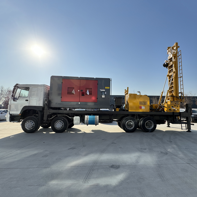
The WRT600 is a truck-mounted straight-mast fully hydraulic water well drilling rig. Its published parameters include a maximum drilling depth of 600 m, a drilling diameter of 140–450 mm, a lifting force of 37 T, an axial pressure of 6 T, a rotary torque of 15000 / 7500 N·m, corresponding to maximum rotation speeds of 70 / 140 r/min, a feed stroke of 7 m, recommended drill pipe diameters of 102 / 114 / 127 mm, drill pipe lengths of 3 m or 6 m, an overall weight of approximately 26 T, transport dimensions of approximately 10 × 2.48 × 3.75 m, and a 132 kW diesel engine. For DTH down-the-hole hammer drilling, the recommended working air pressure is 1.2–3.5 MPa, and the air consumption is 16–55 m³/min. All judgments below are made only within the scope of this information.
Step 1: Determine which hole section the target well depth falls into
In water supply projects, "well depth" usually has three meanings: design well depth, burial depth of the target aquifer, and the additional water-finding margin that must be left below. 600 m is the maximum drilling depth given in the equipment documentation, which does not mean every well must be drilled to 600 m. Only in areas with deep groundwater levels, unstable shallow aquifers, or a need for a larger water-finding margin does 600-meter-class capability make sense. Conversely, if the target aquifer is already stable at around 200 m, the well depth condition itself does not justify selecting this class of equipment.
The output of this step should be a clear hole depth range, and whether this depth is drilled through bedrock or mainly stops in the upper-middle unconsolidated layer.
Step 2: Hole diameter and completion structure determine the load magnitude
The hole diameter range of 140–450 mm covers a variety of completion structures, but agricultural and community water wells usually do not require long-term use of the maximum hole diameter. Only mining, industrial, and high-flow water supply projects may require larger well diameters. The choice of hole diameter should serve the final completion objective: well casing, screen pipe, submersible pump specifications, and expected water yield. The larger the hole diameter, the greater the in-hole load at the same depth, and the requirements for lifting force, torque, and air volume change accordingly.
Items that need to be determined first include: final hole diameter, diameter and material of well casing and screen pipe, position of the sealing section, and whether casing is needed to establish a stable upper hole section. These are not read from an equipment parameter table, but are the results of hydrogeological investigation and well completion design.
Step 3: Check lifting force and torque by operation, not by total amount
The 37 T lifting force and 6 T axial pressure provide margin for drill pipe tripping, down-the-hole hammer recovery, and some casing operations. At 600-meter-class hole depths, the self-weight of the drill pipe, borehole wall friction, and casing weight all increase, so this step depends on the specific operation: how heavy a drill string needs to be run, how many sections the casing is run in, and whether pulling is needed when anomalies occur in the hole. The information also gives one boundary: if abnormal tripping resistance occurs, it should first be handled by judging and addressing hole cleaning and in-hole conditions, and should not rely solely on the maximum lifting force for forced pulling.
The torque item corresponds to two sets of values: 15000 / 7500 N·m and 70 / 140 r/min. Low speed and high torque are more suitable for large hole diameters, hard rock, and high-resistance hole sections, while the high-speed gear is suitable for stable formations with lower resistance. During construction, adjustments should be made dynamically according to rotary load, cuttings return, and drilling tool condition, rather than understanding the two gears as a simple speed choice.
Feed stroke and drill pipe specifications affect construction organization
The feed stroke is 7 m, used with 3 m or 6 m drill pipes. 6 m drill pipes reduce the number of connections and help continuous drilling efficiency; 3 m drill pipes are more suitable for sites with limited space or ordinary transport conditions. The fast lifting speed of 30 m/min and fast advancing speed of 41 m/min are mainly used for drill pipe operations and power head return. These items do not change whether 600 m can be reached, but they affect the number of operations and site rhythm at the same hole depth.
Step 4: Confirm the drilling method by formation combination in sections
Many water wells have unconsolidated overburden in the upper part and gradually transition to weathered rock and intact hard rock in the lower part. The positioning of the WRT600 is precisely that mud rotary drilling or casing wall protection can be used in the upper part, and DTH down-the-hole hammer can be switched to in the lower part.
- Unconsolidated formations such as soil, clay, sand, and gravel layers: a mud pump and suitable drilling tools can be configured for mud rotary drilling. Mud circulation carries cuttings and helps stabilize the borehole wall; when the upper unconsolidated layer is thick, casing can also be combined to establish a stable hole section.
- Relatively intact rock formations: medium- and high-pressure down-the-hole hammers can be configured for DTH drilling. Hard rock construction should ensure down-the-hole hammer lubrication, bit condition, and continuous hole cleaning.
- Strong aquifers and water inflow sections: groundwater will change cuttings discharge in the hole and the working state of the down-the-hole hammer. The depth of the main water-producing layers should be recorded, and air supply, hole cleaning, and casing plans should be adjusted according to water inflow; during completion, screen pipes and sealing sections also need to be set according to aquifer positions.
- Arid and water-scarce areas: in suitable rock formations, DTH down-the-hole drilling mainly relies on compressed air impact and cuttings discharge, with relatively low dependence on large amounts of drilling water; if the upper unconsolidated layer is thick, mud or casing assistance may still be needed.
For DTH drilling, the recommended working air pressure is 1.2–3.5 MPa and the air consumption is 16–55 m³/min. Air compressor selection should consider hole diameter, hole depth, down-the-hole hammer specifications, rock hardness, and altitude at the same time; reaching pressure alone while insufficient in displacement will still cause insufficient impact and difficult cuttings discharge.
Step 5: Go through site access and relocation conditions separately
The WRT600 relies on a truck-mounted chassis for road relocation, making it suitable for frequent movement between multiple project sites and reducing loading and unloading operations. But this step is a different matter from drilling capability: the overall weight is approximately 26 T, transport dimensions are approximately 10 × 2.48 × 3.75 m, and the straight-mast structure requires advance confirmation of road height limits, site clearance and turning space, as well as drilling site ground bearing capacity, bridge load capacity, and road width. The truck-mounted structure reduces loading and unloading operations, but it does not mean it can access any road.
Combine the five steps into a comparison table
| Judgment stage | Items to determine first | WRT600 corresponding published parameters |
|---|---|---|
| Target well depth | Design well depth, target aquifer burial depth, water-finding margin | Maximum drilling depth 600 m |
| Hole diameter and completion structure | Final hole diameter, well casing and screen pipe, sealing section, whether to use casing | Drilling diameter 140–450 mm |
| Lifting and rotation | Drill string weight, casing sections, estimated in-hole resistance | 37 T lifting force, 6 T axial pressure, 15000 / 7500 N·m |
| Drilling method | Upper unconsolidated layer thickness, lower lithology, water inflow conditions | Mud rotary and DTH sectional switching; 1.2–3.5 MPa, 16–55 m³/min |
| Site access and relocation | Road width and height limits, turning radius, site bearing capacity | Approximately 26 T, approximately 10 × 2.48 × 3.75 m |
The reverse order also works
In actual projects, it is also possible to work backward from equipment capability: first confirm whether the 26 T complete machine and straight-mast structure can access the site, then check whether the hole diameter and well casing plan fall within 140–450 mm, and then verify whether the hole depth, lifting force, and torque cover the estimated load. The value of working backward is to expose hard constraints as early as possible—if the site or road stage cannot be passed, subsequent parameter checks are meaningless.
Parts this information does not answer
The published information of the WRT600 does not provide drilling efficiency for specific formations, completed well water yield, cost per unit footage, or penetration rate under different rock conditions, nor does it provide a complete matching list for different combinations of hole depth and hole diameter. Hydrogeological conditions, in-hole tools, drilling angle, and operating methods vary, and the final drilling efficiency, drilling depth, and well completion effect should be based on actual site conditions. Hydrogeological investigation, water quality evaluation, and determination of well depth, well diameter, screen pipe, and pump type for formal projects all need to be completed separately from equipment selection.