












In the WRT1200 documentation, the rotary system is described as "maximum torque 24000/12000 N·m, corresponding to a 75/150 r/min dual-speed configuration." The two rows of values are placed together, making it easy to read them as a speed table: choose high speed for faster operation, choose low speed for more power. However, these two torque figures are each aimed at the resistance state of a certain section within the hole, not at operator feel. Based solely on this set of parameters published on this site, this article explains the hole section conditions under which the two torque ranges respectively fall, and the parts where this set of values cannot by itself define the hole section.
The Two Torque Figures Are Not Two Marks on One Range
24000 N·m and 12000 N·m differ by a factor of two, and the corresponding speeds are 75 r/min and 150 r/min, also differing by a factor of two. The pairing relationship of these two sets of values is: the higher the torque, the lower the speed; the lower the torque, the higher the speed. It describes the upper limit that the same rotary system can output under two operating condition settings, rather than two gears that a single machine can freely switch between up and down within the same hole section.
From this, a constraint direction can be derived: when 24000 N·m output is required, the actual upper limit of rotary speed is 75 r/min; when 12000 N·m output is required, the speed upper limit is 150 r/min. For any hole section, as long as the torque upper limit is used, it means that this section can only be advanced at a lower speed. Conversely, for a hole section advanced at 150 r/min, the available torque upper limit is 12000 N·m.
Hole Section Characteristics Corresponding to the Low-Speed High-Torque Gear
The documentation describes the 24000 N·m/75 r/min gear as "more suitable for large-diameter, hard rock, and high-friction hole sections." Three characteristics are given here, which need to be understood separately.
Large Diameter
The WRT1200's drilling diameter range is 105–900 mm, with 900 mm being the maximum diameter published for this machine. As the hole diameter increases, the contact area between the hole bottom and the drilling tools, the volume of cuttings to be removed, and the required rotary torque all increase simultaneously. The documentation also notes that a larger hole diameter increases drilling tool load, casing weight, cuttings removal demand, and air compressor load. Therefore, "large diameter" itself is a project condition that must be determined together with water yield, well casing, and pump type design; it is not a construction target that can simply be taken to the upper limit.
Hard Rock
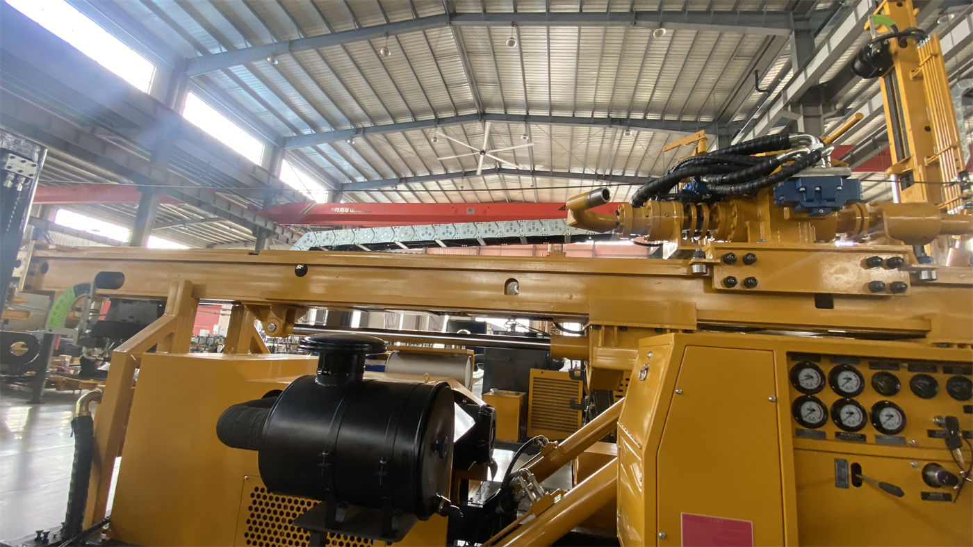
After entering relatively intact hard rock such as limestone, sandstone, and granite, the documentation recommends configuring medium- and high-pressure down-the-hole hammers for DTH drilling. The DTH hammer itself handles the rock-breaking impact, but the rotary system still needs to provide the torque that allows the drill bit to continuously reposition. The resistance nature of this section differs from that of the upper loose layers, so it falls into the high-torque gear.
High-Friction Hole Sections
This item is directly related to hole depth. In 1200-meter-class deep holes, the self-weight of the drill pipe, borehole wall friction, and sediment conditions accumulate with hole depth. In the lifting force section, the documentation states: "If the drill lifting resistance is abnormal, the hole should first be cleaned and the conditions of the borehole wall, drilling tools, and sediment should be assessed; one should not simply rely on the maximum lifting force to pull forcefully." The same judgment logic applies to rotation: the high-torque gear is the upper limit of the ability to cope with resistance, not a routine means to offset accumulated cuttings or borehole wall problems.
Hole Section Conditions Corresponding to the High-Speed Gear
For the 12000 N·m/150 r/min gear, the documentation states that it is "suitable for stable formations with relatively low resistance." Here, "stable" and "relatively low resistance" are a set of conditions that must hold simultaneously.
The meaning of stable formation is correspondingly explained elsewhere in the documentation: soil layers, clay, sand layers, and gravel layers can use mud rotary, casing, or other hole stabilization methods; weathered rock and fault fracture zones are prone to block falling, diameter shrinkage, air leakage, and drill sticking, and when entering such hole sections, excessively fast advancement should be reduced and hole cleaning strengthened. In other words, low resistance is only the result; whether the hole section is stable is the prerequisite for whether the high-speed gear can be used. A low resistance reading may also come from an undersized hole diameter or drilling tool problems, which are two different matters from formation stability.
Gear Selection for Different Hole Sections in the Same Well
Putting the two torque ranges back into the hole sequence of a 1200-meter-class well, it can be seen that the hole sections they correspond to often appear alternately, rather than being selected once and for all. The segmentation methods involved in the documentation include:
- Upper loose layers: mud rotary, casing, or other hole stabilization methods; the resistance nature of this section differs from that of deep rock formations.
- Intact hard rock: medium- and high-pressure DTH hammer drilling, corresponding to high torque and low speed.
- Weathered rock and fracture zones: control advancement, strengthen hole cleaning, and use casing or foam assistance according to borehole wall conditions.
- Main aquifers: groundwater changes the cuttings removal and downhole pressure state of the DTH hammer, and the air supply and hole cleaning plan need to be adjusted according to water inflow.
These four types of hole sections each correspond to different rotary requirements, indicating that the value of the dual-speed configuration lies in enabling the same machine to cover multiple hole sections of one well, rather than enabling a single hole section to achieve twice the efficiency.
Hole Section Information That the Torque Values Alone Cannot Define
24000 N·m and 12000 N·m are the output upper limits of the rotary system; they do not include the following content. This content needs to be supplemented from the project side and cannot be inferred backward from the torque values.
| Information to Be Confirmed | Why the Torque Values Cannot Provide It |
|---|---|
| Start and end depths of hole sections | The documentation only gives the overall maximum drilling depth of 1200 m and the hole diameter range, but does not give the depth correspondence for which gear is suitable for each hole section |
| Drill bit and drilling tool combination | The recommended drill pipe diameter is 127 mm, and the drill pipe length supports 3 m or 6 m, but the actual torque demand corresponding to a specific drilling tool combination depends on the project design |
| Air compressor matching | For DTH conditions, the recommended working air pressure is 1.65–8 MPa and the air consumption is 16–120 m³/min. Insufficient pressure or displacement will affect impact and cuttings removal, thereby changing the rotary load; this layer is not within the torque parameters |
| Mud or foam plan | The documentation mentions multiple hole stabilization methods such as mud rotary, casing, and foam assistance. The impact of medium changes on rotary resistance must be determined by special project design |
In addition, the documentation gives a feed/travel stroke of 7/13 m, which can be selected according to the final configuration; the formal configuration should be based on the supplier's technical confirmation documents. There is no direct conversion relationship between the feed stroke and hole section gear selection; what it affects is the frequency of power head return and drill pipe handling.
The Part Explicitly Stated in the Documentation Regarding Switching Timing
The documentation has a clear construction requirement: "During construction, the operating condition should be switched in a timely manner according to drilling tool load, return cuttings, and torque changes." The criteria given by this statement are three types of on-site signals—drilling tool load, return cuttings state, and torque changes—rather than fixed hole depth values. In other words, when to switch from one gear to another needs to be determined by actual downhole feedback.
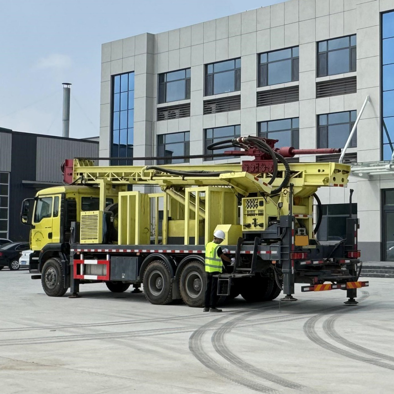
The remaining relevant values are listed together for reference: maximum drilling depth 1200 m, drilling diameter 105–900 mm, lifting force 61 T, axial pressure 13 T, power configuration 220/264 kW, overall weight approximately 32 T, and transport dimensions approximately 11.5×2.25×3.2 m. These parameters each constrain different links, and likewise do not constitute a basis for dividing "a certain torque range corresponds to a certain depth."
Matters Still to Be Confirmed with the Supplier
This article uses only the publicly available WRT1200 information on this site. Items not recorded in the documentation include: the specific operation method and switching conditions for the two torque ranges, the recommended gears under different hole diameter and rock formation combinations, the drilling efficiency differences corresponding to the two operating conditions, and whether different power configurations (220 kW and 264 kW) affect the output capability of the rotary system. These contents should be based on the supplier's technical confirmation documents, and this article does not present them as conclusions.