












The requirements description for a rural water supply well project usually does not just say "drill a well." It comes down to several specific conditions: how deep the well is planned to be, what diameter to use, which formations it will pass through, how the well casing and submersible pump will be configured, whether the equipment can reach the well site, and how the upper loose layer will be handled during completion. Only after these conditions are set does it come to judging whether a certain class of drill is suitable. This article uses the public specifications of the WR260 from this site as a reference, breaking down the requirements that rural water supply well projects place on 260 m class equipment in the order in which the requirements form.
First, the equipment conditions referenced in this article
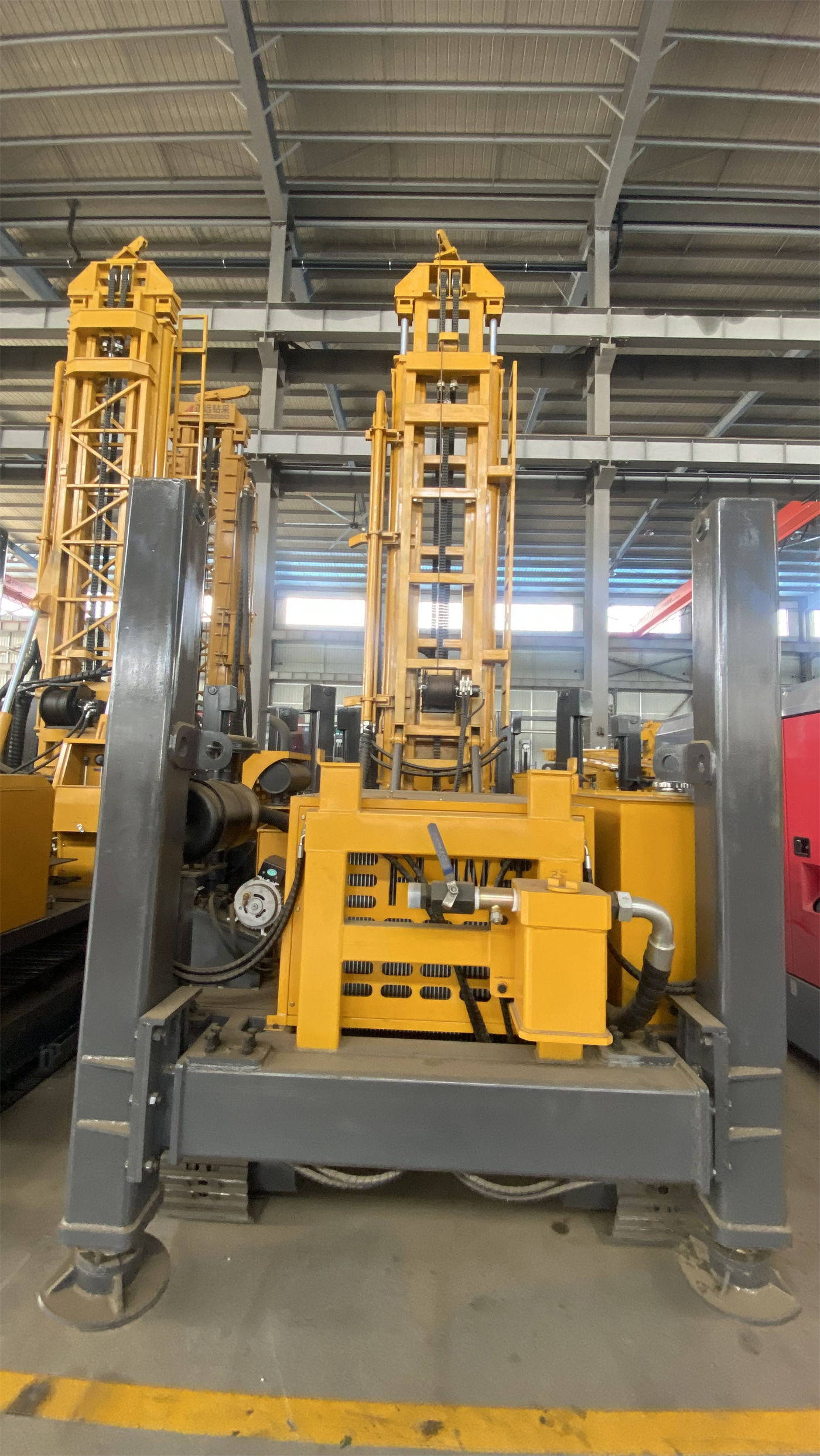
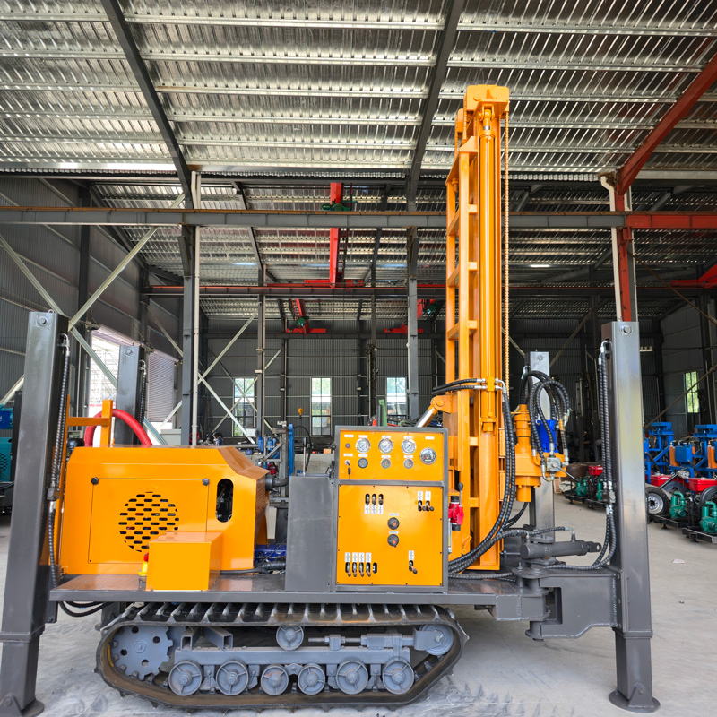
The public information for the WR260 states: compact crawler-type fully hydraulic water well drill, maximum drilling depth 260 m, drilling diameter 140–305 mm, 76 kW diesel power (optional electric motor power also available), rotary torque 4000–5300 N·m, rotary speed 45–70 r/min, lifting force 15 T, single feed length 3.3 m, compatible with 1.5 m, 2 m, and 3 m drill rods, fast lift 24 m/min, fast feed 40 m/min, main drilling method is DTH down-the-hole hammer, when using DTH hammer drilling the reference working air pressure is 1.7–2.5 MPa and air consumption is 17–31 m³/min. Total weight approx. 5.7 T, dimensions approx. 3900 × 1750 × 2250 mm, steel crawler chassis, travel speed approx. 2.5 km/h, reference maximum gradeability 30°, outrigger stroke 1.4 m, auxiliary winch lifting force 1.5 T. The materials also contain a 2.73 m figure labeled "Width of loading," which is inconsistent with the overall width of 1750 mm. This article retains it as originally labeled in the materials without further interpretation, and the final value should be confirmed with formal production technical documentation.
Step 1: Match "260 m class" to the target well depth
The maximum drilling depth of 260 m is the upper limit of hole depth for the equipment under given working conditions. It does not mean the project must drill to 260 m, nor does it mean every project can reach this depth. The target well depth of a rural water supply well is usually determined jointly by the local groundwater level, aquifer burial depth, and water demand. If the completion structure requires a larger value within the 140–305 mm hole diameter range, the actual hole depth achievable by the same equipment often needs to be recalculated; only by including the hole diameter, well casing specifications, and submersible pump model in the requirement description can one judge how much margin the 260 m figure leaves.
Step 2: The hole diameter range determines the load magnitude
The materials give the WR260 drilling diameter as 140–305 mm and state that this range can cover various well casing and submersible pump configurations. Changes in hole diameter affect several things: the specifications of the drill bit and DTH hammer, the volume of rock fragments, the air volume required for cuttings removal, and whether the upper hole section needs casing for wall protection. The materials also state that when hole diameter increases, rock layers harden, or altitude rises, a more ample air flow is usually required. Therefore, hole diameter should not be determined only as a completion requirement but also verified as a supporting condition.
Step 3: Lifting force and torque correspond not to total volume but to operations
The purpose of the 15 T lifting force is stated very specifically in the materials: normal tripping, drill rod handling, DTH hammer recovery, and some casing operations. Rural water supply wells often require casing under loose overburden, or casing to protect unstable upper hole sections in weathered rock. Whether this section falls within what 15 T can cover needs to be verified separately based on casing specifications, running depth, and hole wall friction. The rotary torque of 4000–5300 N·m covers conventional DTH drilling; after entering intact hard rock, the materials advise adjusting rotation and feed according to rock hardness, DTH hammer specifications, and cuttings removal status, maintaining coordination among impact, rotation, and air supply. The torque value itself cannot replace judgment of the downhole resistance state.
Step 4: Formation combination determines how drilling methods are segmented
The common formation profile of a rural water supply well is upper loose overburden, middle weathered rock or alternating soft-hard layers, and lower intact bedrock and aquifer. The public materials for the WR260 provide explanations for these formation types respectively:
| Formation Type | Corresponding Treatment in Materials |
|---|---|
| Soil, clay, sand, gravel overburden | Direct use of DTH hammer may cause hole collapse and buried drill; casing, mud, or other hole stabilization techniques should be selected according to formation, first establishing a stable hole opening and upper hole section |
| Weathered rock, alternating soft-hard formations | Watch for hole wall falling blocks and diameter reduction; adjust feed and rotation as drilling resistance changes; use casing to protect unstable upper hole sections when necessary |
| Relatively intact rock such as limestone, sandstone, granite | Can be used for drilling after matching with suitable DTH hammer, drill bit, and air compressor; pay attention to drill bit wear, DTH hammer lubrication, and cuttings removal status |
| Fracture zones, fracture-developed formations | Reduce excessive feed, maintain cuttings removal and hole cleaning, observe air pressure changes; for thicker fracture zones consider casing or foam assistance |
| Aquifers and strong water inflow conditions | Groundwater will change DTH hammer operation and rock powder discharge status; adjust air supply and hole cleaning methods, record main aquifer depths |
| Karst caves, open fractures, severe air leakage formations | Pressure and flow may be difficult to effectively transmit to the hole bottom; consider foam, casing, increased air volume, or changing construction methods |
Step 5: Completion structure should be listed separately
The completion structure of a water supply well includes well casing, screen pipe, sealing sections, and gravel packing design. The WR260 materials state when discussing aquifers: after entering the aquifer, adjust air supply and hole cleaning methods according to water inflow, and record the main aquifer depth; during formal completion, reasonably configure well casing, screen pipe, and water stop structure according to aquifer position. The materials also advise that before completion, the well depth, diameter, screen pipe, and sealing sections should be determined based on aquifer position, expected water yield, and local water quality requirements. These are not equipment parameters, but they in turn constrain what actions the equipment must complete in a certain hole section, such as casing running depth, screen pipe position, and whether drilling must stop at a certain depth.
Step 6: Go through site access and site conditions separately
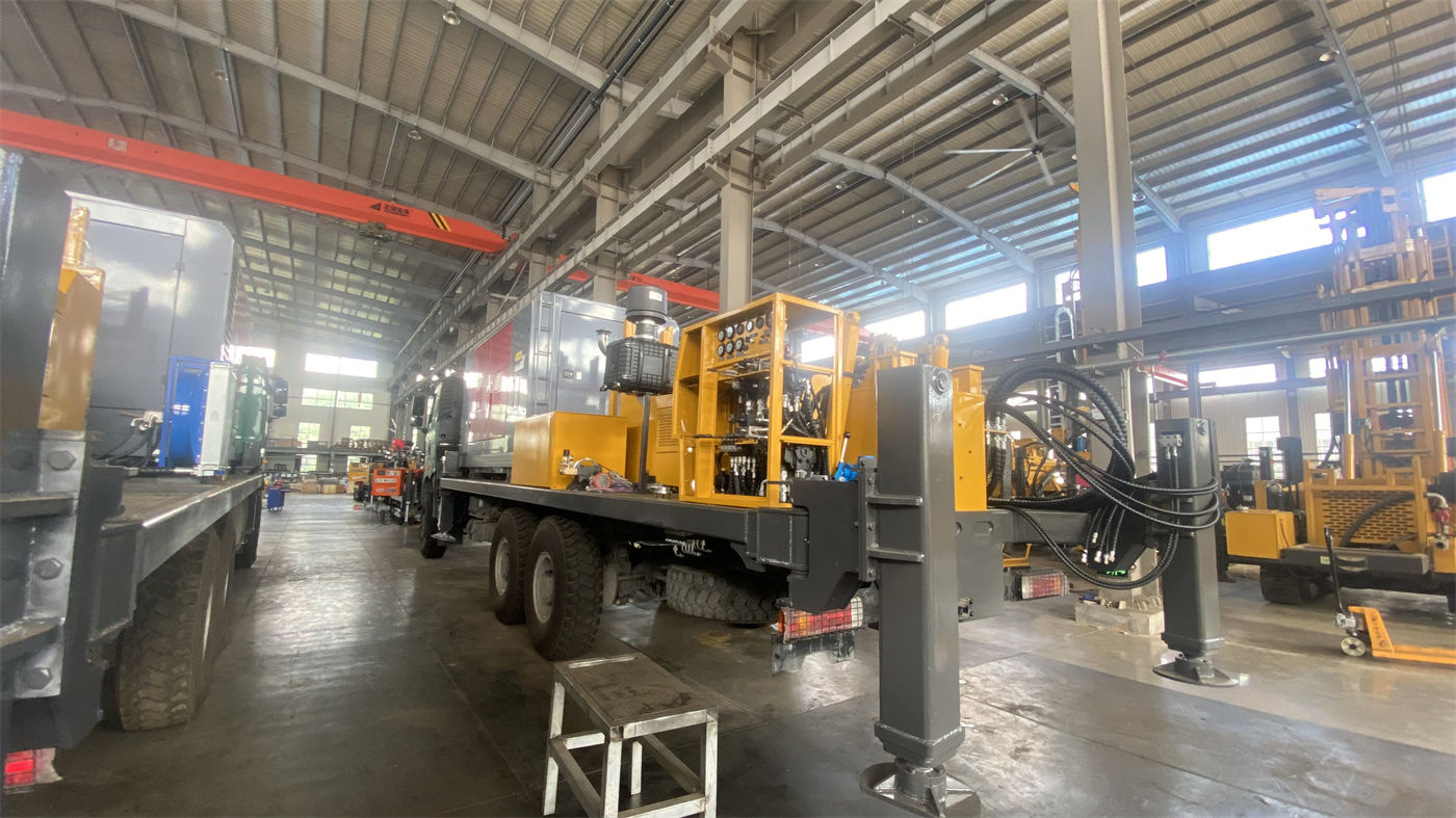
The well site of a rural water supply well is often located beside a village road, in a field, or near a courtyard. The WR260 steel crawler chassis is suitable for gravel ground, rural roads, and mining site areas, with a travel speed of approx. 2.5 km/h and reference maximum gradeability of 30°. The materials advise for relocation: when relocating, retract the mast and assess slope and ground bearing conditions. The outrigger stroke of 1.4 m can be used for support and leveling on slightly uneven ground; soft ground requires additional pads to prevent outrigger settlement causing mast tilt and hole position deviation. The total machine is approx. 3900 × 1750 × 2250 mm and weighs approx. 5.7 T. This set of dimensions and weight places specific requirements on village road width, field road bearing capacity, and transportation methods, and the route should be checked before entering the site. The "2.73 m loading width" item in the materials is inconsistent with the overall width; the transportation plan should not directly cite this value and must confirm with production technical documentation.
Step 7: Air compressor and supporting equipment are not in the overall machine parameter table
The WR260 main drilling method is DTH down-the-hole hammer, and the materials give reference working air pressure 1.7–2.5 MPa and air consumption 17–31 m³/min. These values indicate that the air compressor is an independent supporting condition in this process, not a capability built into the machine. The materials clearly state: insufficient air compressor displacement will cause insufficient DTH hammer impact and difficult cuttings removal; when hole diameter increases, rock layers harden, or altitude rises, a more ample air flow is usually required. When inquiring about a project, the air compressor's displacement, pressure rating, accompanying method, and fuel or power supply are all conditions that must be settled together with the main machine. If the project has a high proportion of hard rock, the materials also advise focusing on matching the DTH hammer and air compressor.
Step 8: Beyond these, parts requiring separate confirmation
The following items are not given explicit values in the WR260 public materials and need to be confirmed at the project level or in formal technical documentation; they should not be inferred on one's own:
- The correspondence between completion well diameter and well casing outer diameter, and the specific configuration of screen pipe and water stop sections;
- The criteria for determining whether to use casing, mud, or other hole stabilization techniques in loose overburden;
- The actual achievable drilling depth margin under different well diameters and different lithology conditions;
- The power, voltage, and control method of the optional electric motor power; the materials only state "optional electric motor power" without giving specific parameters;
- The actual meaning of the "loading width 2.73 m" label, which must be based on formal production technical documentation;
- The specific impact of local water quality requirements for rural water supply wells on screen pipe material selection and completion techniques.
After going through the above conditions in order, whether a 260 m class drill is suitable for a particular rural water supply well usually does not have an answer of "yes" or "no," but depends on how much margin the target well depth leaves, what range the hole diameter falls into, how the upper loose layer is handled, whether the air compressor support is in place, and whether the equipment can enter the site smoothly. The WR260 public specifications provide a starting point for these verifications; the final drilling efficiency, drilling depth, and completion results should still be based on on-site working conditions.