












The public specifications for the WR750S present multiple sets of values at the same time: maximum drilling depth 750 m, hole diameter 105–450 mm, lifting force 40 T, axial pressure 6 T, rotary torque 13000/6500 N·m or 15000/7500 N·m, maximum rotation speed 95/190 r/min, recommended 102 mm drill pipe and 6 m drill pipe length, working air pressure 1.6–6 MPa, air consumption 16–75 m³/min, and overall weight approximately 14 T. When these numbers appear side by side, they are most easily read as a checklist of capabilities that can be ticked off item by item. But they have referential relationships: drilling depth changes drill string weight, drill string weight changes the lifting force margin, hole diameter and rock formation determine which torque setting should be used, and whether the DTH hammer can work depends on the air compressor configuration beyond the pressure and displacement listed in the underground column. This article focuses only on these relationships and does not introduce data outside the specifications.
Group 1: 750 m and 6 m drill pipe—first look at the number of pipe connections
The 750 m maximum drilling depth and 6 m drill pipe length are written in the same specification. When these two items are placed together, the more intuitive inference is the order of magnitude of pipe connection operations. Estimating at 6 m per section, drilling to 750 m means over a hundred make-up and break-out operations. The specifications also state that the S in the model represents a telescopic mast, which supports direct operation with 6 m drill pipe and 6 m casing in working condition, and retracts the mast in transport condition to improve the overall transport profile.
What can be read from this group is: the combination of 6 m drill pipe and telescopic mast points to reducing auxiliary time caused by each pipe connection operation, rather than changing single-pass drilling capability. The specifications do not give the time per pipe connection, nor do they give statistics on auxiliary time for a whole well, so construction period cannot be estimated from this; it can only be confirmed that the structure is designed for long drill pipe operation.
Group 2: Hole diameter 105–450 mm and two torque configurations
The specifications give a hole diameter range of 105–450 mm, and the rotary system has two configurations: 13000/6500 N·m and 15000/7500 N·m, corresponding to maximum rotation speeds of 95/190 r/min. The relationship between these two types of values needs to be considered together with hole diameter and rock formation.
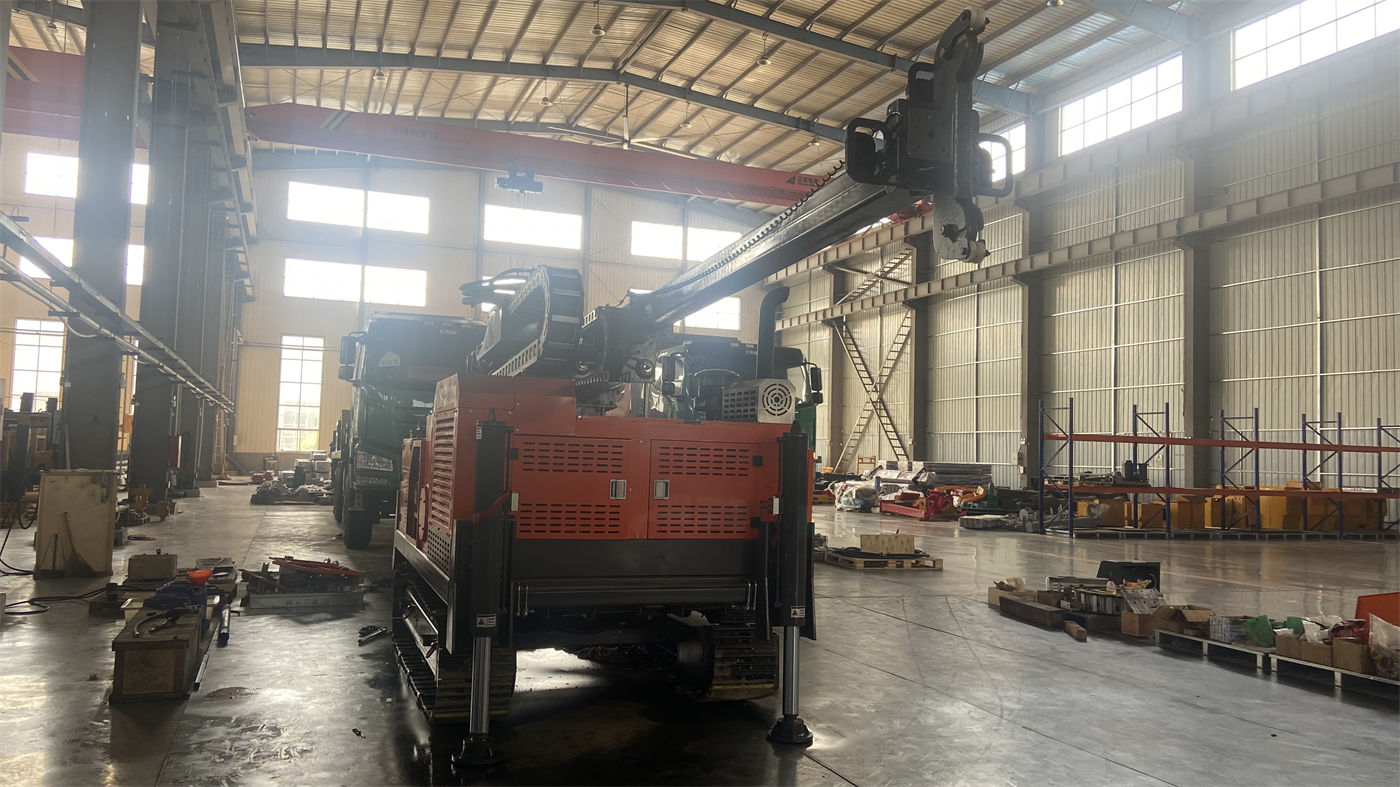
- The larger the hole diameter, the larger the contact area at the hole bottom, and the torque required for rotation increases accordingly, so large-diameter hole sections rely more on the configuration with higher torque reserve.
- In the lower hole diameter range (about 105 mm) under lower resistance conditions, the higher rotation speed setting has more room for use.
- The specifications state side by side that “a larger torque reserve is more suitable for large-diameter, hard rock, and high-friction hole sections” and that “higher rotation speed is suitable for drilling stages with relatively lower resistance,” but they do not provide a correspondence table between hole diameter and torque setting.
In other words, this group of values can explain the difference in orientation between the two configurations, but cannot indicate that a specific hole diameter must correspond to a certain torque setting. What the specifications make clear is that “the final rotary configuration should be determined according to hole diameter, drilling tools, and main rock formation,” and this judgment must be completed at the project level.
Group 3: 40 T lifting force and long drill string weight
Lifting force 40 T, axial pressure 6 T. As hole depth increases, the self-weight of the entire drill string and wall friction both rise. The margin provided by 40 T corresponds to the processes of tripping in and out, DTH hammer recovery, and partial casing handling. The specifications specifically state a boundary here: if abnormal pull-out resistance occurs, it should first be handled by cleaning the hole, lifting slowly, and judging downhole conditions; the maximum lifting force should not be treated as the only means.
What needs to be understood separately in this group is: lifting force is the upper capability limit provided by the equipment, while what handling path to take when abnormal resistance occurs is a construction judgment, and the specifications themselves do not provide handling steps. What can be confirmed here is the position of the value, not that a certain downhole condition will definitely allow the drill string to be pulled out.
Group 4: 1.6–6 MPa air pressure and 16–75 m³/min air consumption
The specifications recommend working air pressure 1.6–6 MPa and air consumption 16–75 m³/min, compatible with medium- and high-pressure DTH hammers. There are two layers of values to distinguish here: the air pressure range is the pressure range required for normal operation of the DTH hammer, and air consumption is the displacement that must be continuously supplied under the same working condition. The specifications clearly point out that if pressure meets the requirement but displacement is insufficient, insufficient impact and difficult cuttings removal may still occur.
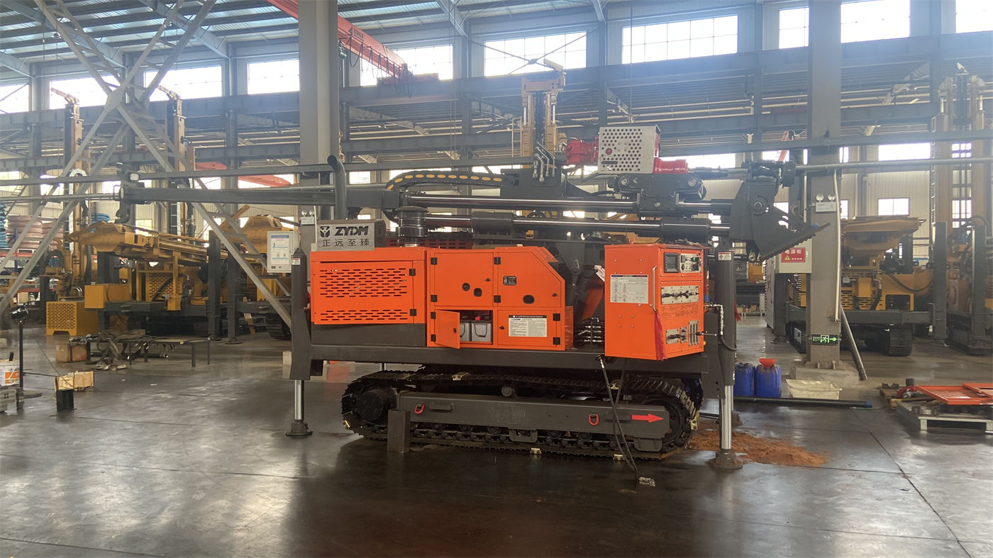
From this it can be read that: the air compressor needs to satisfy both pressure and displacement, not just one of them. The specifications do not state which model of air compressor is supplied with the machine, and the specific model and configuration of the air compressor need to be separately implemented at the project level. Under 750 m deep hole, large diameter, and high altitude conditions, the specifications indicate that whether displacement is sufficient is particularly important.
Group 5: Overall 14 T and transport dimensions
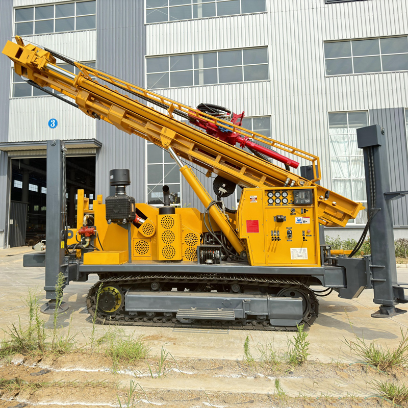
The specifications give an overall weight of approximately 14 T and dimensions of approximately 6.64 × 2.25 × 2.67 m, and indicate that cross-project transport should confirm flatbed load capacity, road width and height limits, and equipment fixing points; the telescopic mast must be in a reliably locked state, and 6 m drill pipe and casing should be secured separately. The relationship between this group of values and the earlier drilling depth and drill pipe length is: 6 m drill pipe and casing are not part of the overall transport profile and require separate transport arrangements.
Travel speed of approximately 3 km/h, maximum climbing angle reference 21°, and hydraulic outrigger stroke 1.6 m are related to site conditions in the specifications. The specifications indicate that travel risks should be strictly controlled in soft soil, slopes, and wet slippery areas, and that sufficient-area pads should be used on soft ground. This group does not give specific bearing capacity requirements and needs to be verified on site.
Putting these values back on the same chain
The relationships among the above groups of values can be linked in one order: target well depth affects total drill string weight and number of pipe connections; well diameter and rock formation affect the choice of rotary torque setting; drill string and downhole friction affect lifting force margin; after entering hard rock, switching to a DTH hammer brings in the two independent conditions of pressure and displacement; finally, relocation and entry conditions are constrained by overall weight and dimensions. Looking at any one item alone is not enough to determine the configuration, which is exactly why what the specifications provide is partly orientation judgment rather than a correspondence table.
There are also several items in the specifications that this article has not expanded on: optional mud pumps, centrifugal pumps, generators, and foam pumps correspond to different formation combinations; the specifications only point out that projects with more loose layers rely more on the mud system, and formations with severe air leakage may require foam assistance; for filter pipes and water-stop sections during well completion, the specifications also mention that they should be based on aquifer distribution, but do not give specific design parameters. These items need to be separately confirmed at the project level and cannot be directly derived from the existing values.
Places where it is easy to overstep when reading these specifications
- Treating 750 m as the target depth for every well. The specifications themselves state that 750 m is the equipment's maximum reference capability, and before formal construction a more reasonable target horizon should be determined based on regional hydrogeological data.
- Treating the two torque configurations as fast and slow feel settings. The specifications describe them together with hole diameter, hard rock, and high-friction hole sections, and the basis for selection is downhole conditions.
- Treating the 40 T lifting force as a solution for abnormal downhole conditions. The specifications give the opposite indication in the same paragraph.
- Describing geological applicability as applicable to the entire hole. The specifications list soil, clay, gravel, weathered rock, fractured zones, fissures, and aquifers separately, and the corresponding treatment methods differ for each section.
The specifications do not give drilling speed, well completion period, or actually achievable completed well depth for each model in specific formations. When reading, this part should be left in the position of “to be confirmed according to project conditions” rather than inferred from the parameter table.