












In the public documentation for the WR600S, the rotary system is written as "maximum torque 12000/6000 N·m, corresponding to maximum rotation speed 90/180 r/min." With the two rows of values placed together, the easiest reading is to treat it as a two-speed gearbox: shift to high speed when you want speed, shift to low speed when you want power. But this set of numbers does not describe operator feel; it describes rotary output under different downhole resistance states. Understanding it as gears will cause the real basis for selection—hole diameter, rock formation, and cuttings return conditions—to be overlooked in actual construction.
First, put the two values back into the same document
The original wording in this site's WR600S documentation is: rotary system maximum torque 12000/6000 N·m, corresponding to maximum rotation speed 90/180 r/min. The same document also states maximum drilling depth 600 m, hole diameter 105–400 mm, lifting force 35 T, axial pressure 6 T, as well as recommended drill pipe diameter 89/102 mm and drill pipe length 6 m. These values form a chain of reference: the deeper the hole, the larger the hole diameter, and the harder the rock formation, the greater the drill string weight and borehole wall friction, and the higher the torque the rotary system needs to output.
The document gives a direct statement on usage: "Actual construction should be dynamically adjusted according to the drill bit, DTH hammer, cuttings return, and rotary load." This sentence already points out that the basis for switching between the two torque values lies downhole, not at the control panel.
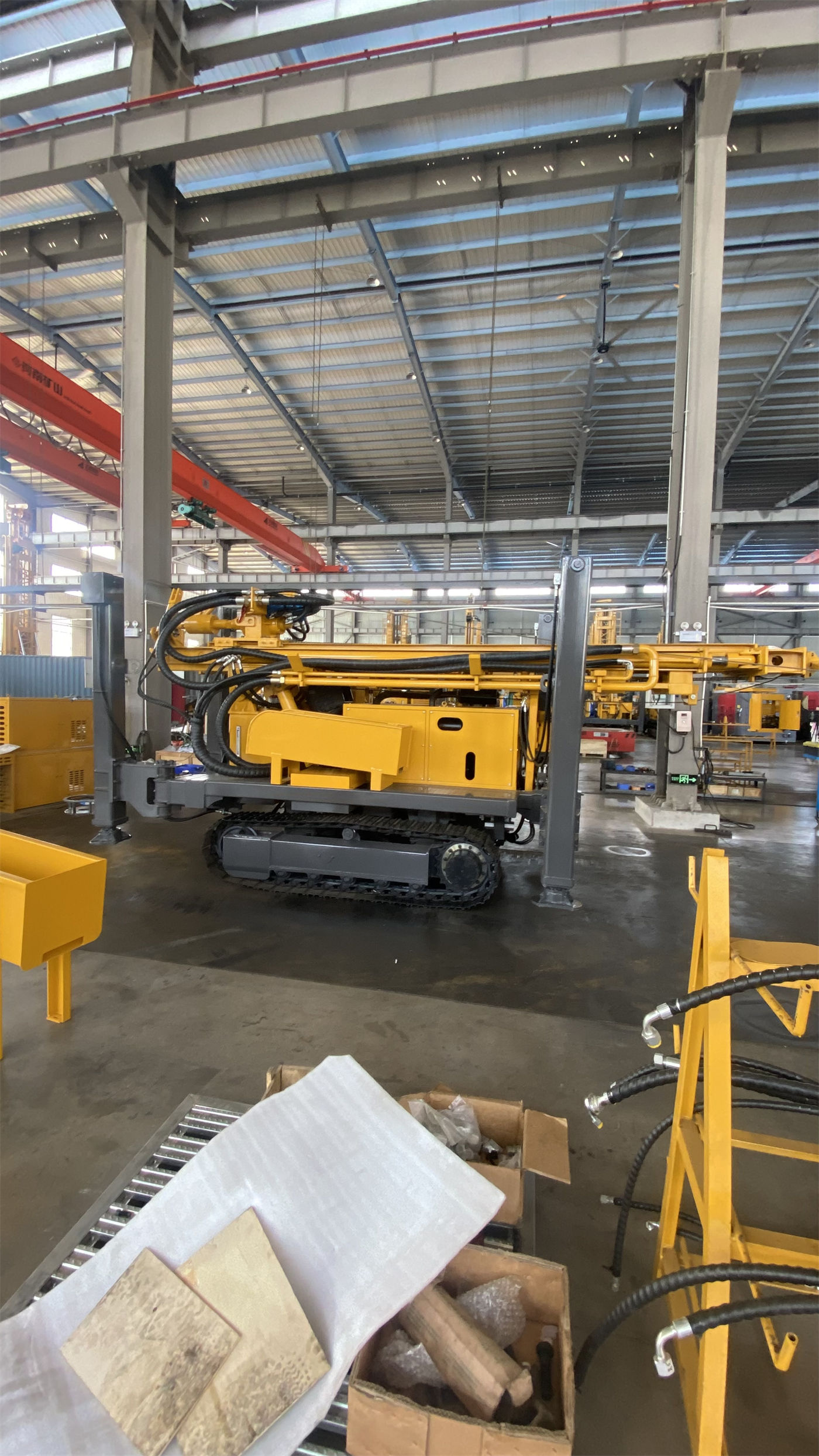
What type of hole section does low-speed high-torque correspond to
According to the document, "larger hole diameters, hard rock, and high-friction hole sections are more suitable for the low-speed high-torque state." Breaking these three conditions down:
- Larger hole diameter—within the 105–400 mm range, the larger the hole diameter, the greater the bottom-hole contact area and cuttings discharge volume, and the higher the rotary resistance.
- Hard rock—the document states that medium and high air pressure DTH hammers can be matched to penetrate relatively intact hard rock, and the drill bit resistance in hard rock sections is directly reflected in the rotary load.
- High-friction hole sections—in deep holes, drill pipe self-weight, borehole wall friction, and local diameter reduction all push up rotary resistance.
The common point of these three conditions is that the resistance comes from downhole and may change from one hole section to another; it is not a gear that remains fixed once selected.
Hole section conditions corresponding to the higher rotation speed range
For the other direction, the document gives only one sentence: "When resistance is low or the drilling tool load is light, a higher rotation speed can be selected." The document does not list item by item which hole sections belong to this category. According to the formation descriptions in the same document, after entering weathered rock, "penetration is often faster," while in alternating soft and hard formations, "rotary torque and thrust resistance change frequently." These statements only indicate that hole sections with lighter resistance exist; they cannot be used to conclude that a certain type of formation is suitable for the high-speed range throughout.
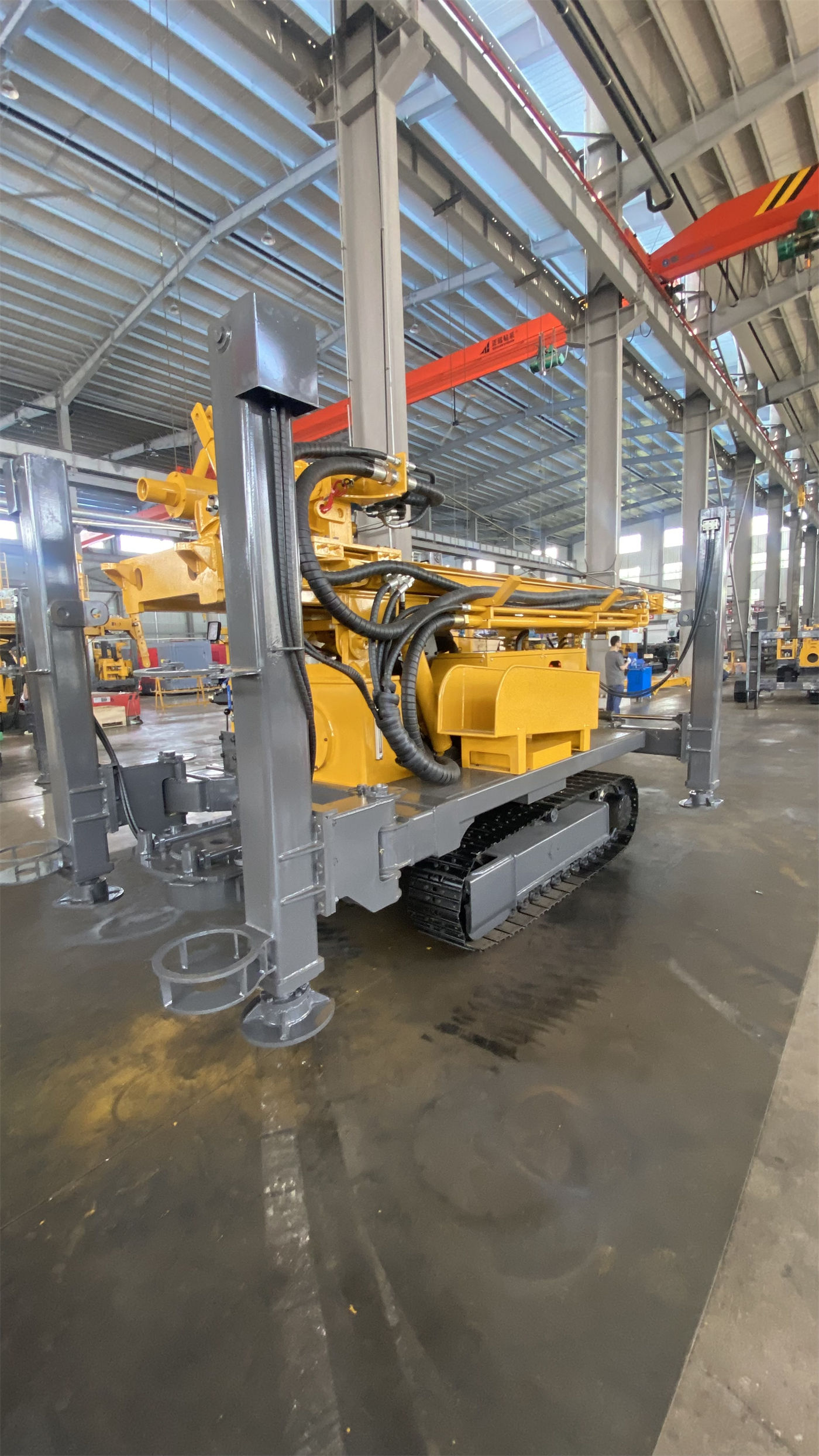
In the same well, the two torque ranges correspond to different hole sections
A 600-meter-class borehole usually passes through more than one formation. The situations listed in the document include weathered rock and alternating soft and hard formations, soil and gravel overburden, fractured broken zones, aquifers, and strong water inflow hole sections. These hole sections place inconsistent demands on the rotary system. According to the document's phrase "dynamic adjustment," the torque range follows the downhole resistance state, rather than being fixedly assigned to a certain drilling stage.
| Hole section characteristics | Corresponding wording in the document | Reference direction for torque range |
|---|---|---|
| Larger hole diameter, relatively intact hard rock | "More suitable for the low-speed high-torque state" | 12000 N·m side |
| Low resistance, light drilling tool load | "A higher rotation speed can be selected" | 6000 N·m side |
| Alternating soft and hard, fractured broken zones | "Rotary torque and thrust resistance change frequently" | Adjust according to downhole conditions |
This table is a categorization based on the original document text, not a switching timetable that can be directly applied. The actual switching point still needs to be judged in combination with on-site cuttings return, torque, and air pressure readings.
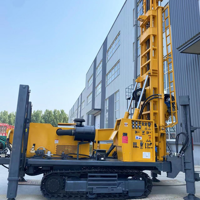
What the two torque values themselves cannot define
12000 N·m and 6000 N·m are the output limits of the rotary system; they cannot answer the following questions on their own:
- Which range to use for a given hole diameter—the document only says "larger hole diameters" are more suitable for low-speed high-torque, without giving a boundary corresponding to a specific millimeter value.
- Which range to use for a certain type of rock formation—the document states that hard rock is suitable for low-speed high-torque, but does not label each rock type.
- When to switch between the two ranges—the document describes this as "dynamic adjustment," and the switching timing falls within the scope of on-site judgment.
- How torque and air compressor displacement coordinate—in the document, working air pressure is 1.2–3.5 MPa and air consumption is 16–55 m³/min, which belong to a different set of parameters from rotary torque, and no linkage relationship is given.
Where reading this set of values easily goes beyond bounds
Reading 12000/6000 N·m as two gears that can be switched at any time is not a problem of misremembering the numbers, but of moving the basis for selection from downhole conditions to operating habits. In the document, alongside torque are lifting force 35 T, axial pressure 6 T, fast lifting 33 m/min, and fast thrust 55 m/min; these parameters each correspond to different operations. Understanding them separately is closer to the document's wording than merging several values into one "capability level." Exactly which range a specific project should lock into and where the switching point should be set are matters that need to be confirmed separately in combination with on-site conditions.