












Water wells for mine water supply are usually not completed with just one hole. They must simultaneously serve domestic water use, dust suppression, equipment cleaning, and auxiliary production, making stable water supply more critical than single-hole penetration. This means that before a crawler drill is moved to the site, several conditions need to be put on paper rather than addressed after the equipment is in place. The following uses the public specifications of the HJH WR500S as a sample to explain these conditions; other models can be self-checked in the same order.
What Conditions Differ Between Mine Water Wells and Ordinary Rural Water Wells
Rural deep water wells and farmland irrigation wells have relatively dispersed hole locations and large variations in single-hole depth, so equipment mobility is often the primary consideration. Mine water supply is different: hole locations are usually concentrated near production or living areas, the single-hole water supply scale is larger, the proportion of intact rock formations may be higher, and the impact of mine roads, blasting areas, and existing pipelines on the site must also be considered.
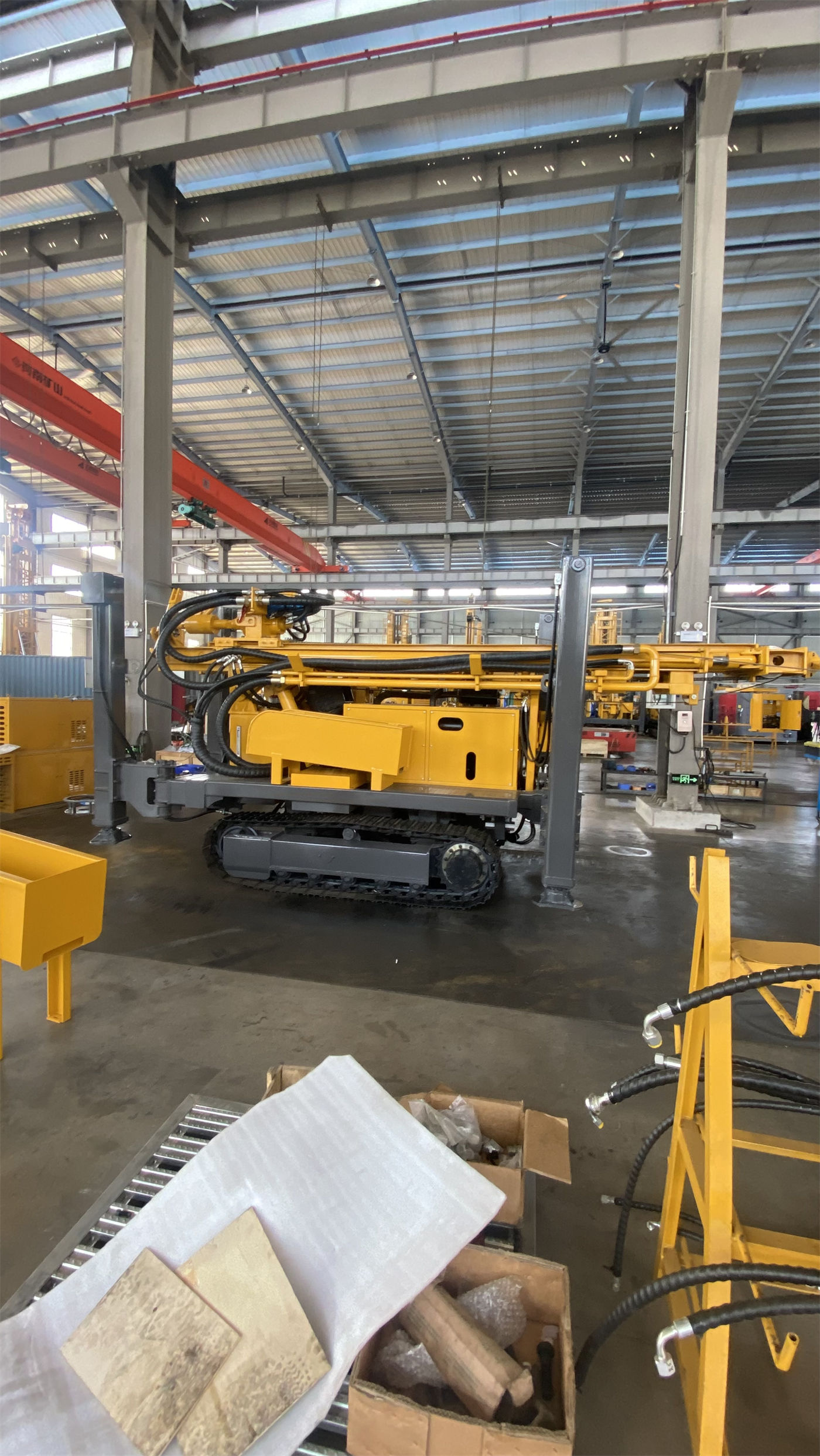
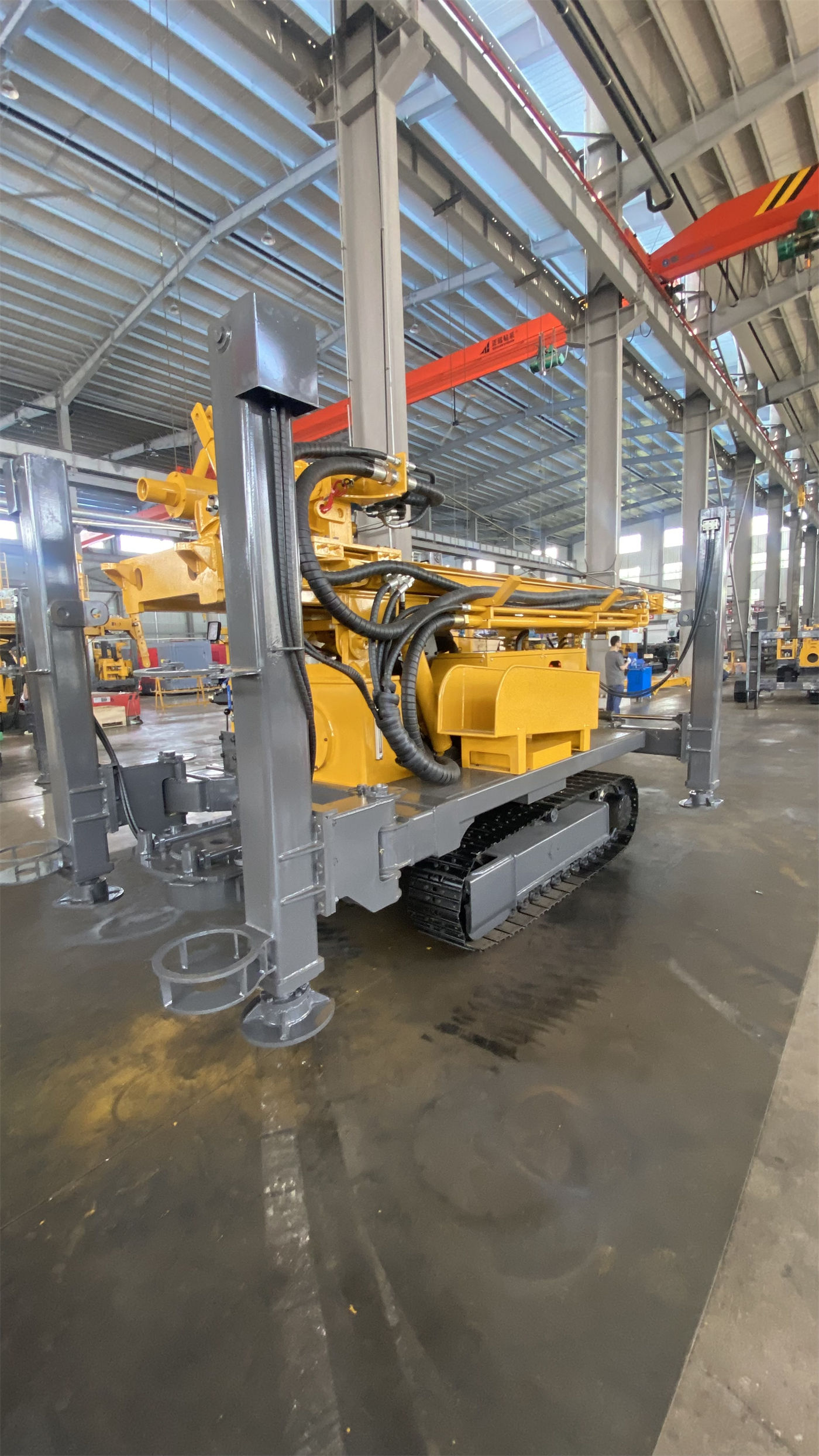
According to the public information of the WR500S, the maximum drilling depth is 500 m, the drilling diameter is 105–400 mm, the crawler chassis travel speed is about 3 km/h, the maximum climbing angle is referenced at 21°, the overall weight is about 10.6 T, the dimensions are about 6.52 × 1.85 × 2.51 m, and the hydraulic outrigger stroke is 1.6 m. Combined, these figures indicate that it can cover the hole depth and diameter requirements of medium-to-deep mine water supply wells, but they also indicate that site entry conditions need to be calculated separately.
Site and Transfer: A Crawler Chassis Does Not Mean It Can Travel on Any Road
The crawler structure has advantages over wheeled types on mine gravel roads and generally uneven ground, but the drill is not an unconditionally all-terrain device. The ground pressure of the approximately 10.6 T overall weight needs to be absorbed by the ground bearing capacity. The 21° figure is only a reference climbing angle; wet, slippery, and loose slope conditions can make this number meaningless.
- The width, slope, and turning radius of the access road need to be calculated based on the dimensions in transport state, not in travel state.
- Mast deployment requires additional space. The telescopic mast can be shortened during transport, but after arriving at the site, space must be reserved for the mast to fully deploy and lock.
- If the ground around the hole location has already been disturbed by blasting or heavy vehicles, additional pads should be placed under the outriggers to avoid settlement after long-term loading.
Formation Structure Determines the Method, Not the Other Way Around
The WR500S supports DTH hammer drilling and mud rotary drilling, and the method can be switched according to the sequence of upper loose layers and lower rock layers. In mine water supply projects, this switch point usually occurs where the overburden enters bedrock, but the specific depth must be determined by on-site formation judgment.
Intact Rock Sections
After entering relatively intact rock, medium- and high-pressure DTH hammers and bits can be used. The recommended working air pressure for the WR500S is 1.2–3.5 MPa, with air consumption of 16–55 m³/min. The information already states that when the hole diameter increases, the rock becomes harder, the hole depth increases, or the altitude rises, the required air compressor displacement will be higher.
Weathered Rock and Alternating Soft-Hard Formations
These formations are easy to drill, but the hole wall may be unstable. When alternating soft and hard layers are encountered, parameters need to be adjusted according to changes in rotary torque and feed resistance. If the upper weathered layer is thick, casing or mud can be used to stabilize the hole.
Soil, Clay, Sand, and Gravel Overburden
The upper overburden can be stabilized through mud circulation, casing, or other hole stabilization measures before entering rock for DTH. For deep water wells, whether the upper hole section is stable is often more important than the penetration rate in this section.
Fracture Zones, Fissures, and Air-Leakage Formations
Fracture zones may cause block falling, air leakage, sticking, and abnormal cuttings return. When air loss is obvious, it should be determined whether large fissures or cavities exist, rather than simply increasing air compressor pressure. The information mentions that foam or casing can be used according to on-site conditions.
Air Supply Support: Working Pressure and Air Consumption Must Be Checked Together
If a mine water supply well enters hard rock and uses the DTH method, an air compressor is necessary support, not optional. The public information for the WR500S gives a reference of working pressure 1.2–3.5 MPa and air consumption 16–55 m³/min. These two figures must be considered together: if pressure is met but displacement is insufficient, bottom-hole cuttings removal will lag; if displacement is met but pressure is insufficient, the DTH hammer will not operate correctly.
Note that the information does not provide a correspondence table for the air compressor displacement required for specific projects. Actual selection must be confirmed with the manufacturer based on hole diameter, hole depth, altitude, and rock formation conditions.
Hole Stabilization and Well Completion: The Long-Term Effect of Mine Water Supply Wells Depends on This Step
Completing the drilling does not mean the water well is usable. After entering the main aquifer, groundwater will change the cuttings return state in the hole and the working conditions of the DTH hammer. At this point, the aquifer depth should be recorded, and the air supply, hole cleaning, and casing plan should be adjusted accordingly. In the well completion stage, filter pipes and sealing layers should be set according to the aquifer position.
The public information for the WR500S mentions optional mud pumps, centrifugal pumps, generators, and foam pumps. Projects with a high proportion of loose layers rely more on the mud system, hard rock projects rely more on air compressors and DTH hammers, and formations with severe air leakage may require foam assistance. Selecting equipment according to actual working conditions is more practical than equipping everything.
Power and Continuous Operation Conditions
The WR500S uses a 110 kW Yuchai engine to provide power for rotation, feed, crawler travel, and auxiliary hydraulic systems. The single-hole construction cycle for mine water supply may be long, and the maintenance frequency of engine cooling, air filtration, and fuel systems needs to be adjusted according to on-site dust conditions: in dusty sites, the cleaning interval for radiators and filter elements will be significantly shortened.
Several Groups of Parameters That Must Be Read Together
| Parameter | Value | Related Judgment |
|---|---|---|
| Maximum drilling depth | 500 m | Covers medium-to-deep water supply well requirements, but does not mean every well is drilled to 500 m |
| Drilling diameter | 105–400 mm | Hole diameter design is related to expected water yield, well casing size, and submersible pump specifications |
| Lifting force | 30 T | Deep-hole tripping, DTH hammer recovery, and some casing operations require calculating drill string weight and hole wall friction |
| Rotary torque | 11000 / 5500 N·m | Corresponds to maximum rotary speeds of 75 / 150 r/min; select working conditions according to hole diameter and rock formation |
| Working air pressure | 1.2–3.5 MPa | Must be checked together with air consumption of 16–55 m³/min |
| Overall weight | About 10.6 T | Affects transport arrangements and access road bearing calculations |
Items Worth Confirming One by One Before Entering the Site
Confirming the following items before the equipment arrives saves more time than handling them after arrival:
- Whether the width, slope, turning radius, and road bearing capacity of the access road meet the passage requirements for transporting an approximately 10.6 T machine with dimensions of 6.52 × 1.85 × 2.51 m.
- Whether there is enough space around the hole location to deploy the telescopic mast and reserve areas for drill pipe placement and lifting operations.
- Whether the construction area is close to blasting areas or existing pipelines and whether additional coordination for avoidance is needed.
- The altitude of the project location and whether the air compressor displacement selection needs to be adjusted accordingly.
- The expected depth of the main aquifer and water inflow conditions, so that filter pipes, sealing layers, and casing plans can be arranged in advance.
- Whether on-site power generation is needed or whether an optional generator can solve auxiliary power needs.
These conditions cannot be judged solely from equipment parameters and need to be verified item by item with the manufacturer based on project geological data and on-site survey results. Actual drilling efficiency, drilling depth, and well completion effects are affected by geological conditions, downhole tools, drilling angle, and operating methods, and should be based on on-site working conditions.