












The borehole locations for mining water supply wells are often not on level ground. Gravel yards, the edges of spoil banks, and open areas beside haul roads may all be designated as well sites. The challenge these places pose to the crawler chassis is not just 'uneven ground.' Ground pressure, slope, voids between gravel, loose surface layers after rain, and settlement beneath outriggers each constrain different stages. Using the published parameters of the WR500S as a reference, this article breaks down the actual constraints on the crawler chassis on gravel sites in mining areas.
First, the verifiable chassis parameters
The WR500S is a 500-meter-class telescopic mast crawler-mounted fully hydraulic water well drilling rig. The publicly available figures related to site traversability are: travel speed approximately 3 km/h, maximum climbing angle reference 21°, overall weight approximately 10.6 T, dimensions approximately 6.52 × 1.85 × 2.51 m, and hydraulic outrigger stroke 1.6 m. The documentation also states: the crawler structure is suitable for gravel roads in mining areas, rural roads, and generally uneven sites; during relocation, ground bearing capacity, slope, and wet/slippery conditions should be confirmed as priorities.
These values describe the equipment's travel and support capabilities, not an admission judgment for any specific site. Below, they are placed back into the actual stages of a gravel site in a mining area.
Travel speed constrains relocation time, not in-hole pace
The travel speed of approximately 3 km/h corresponds to the equipment moving itself between borehole locations within the mining area, or from a temporary parking spot to the borehole. At this speed, a distance of 1 km takes about 20 minutes of travel time, not yet including time for route finding, avoidance, slowing on slopes, and positioning. In mining water supply projects with scattered boreholes, this time must be counted separately in shift planning; it is not the same category as the time required for in-hole drilling.
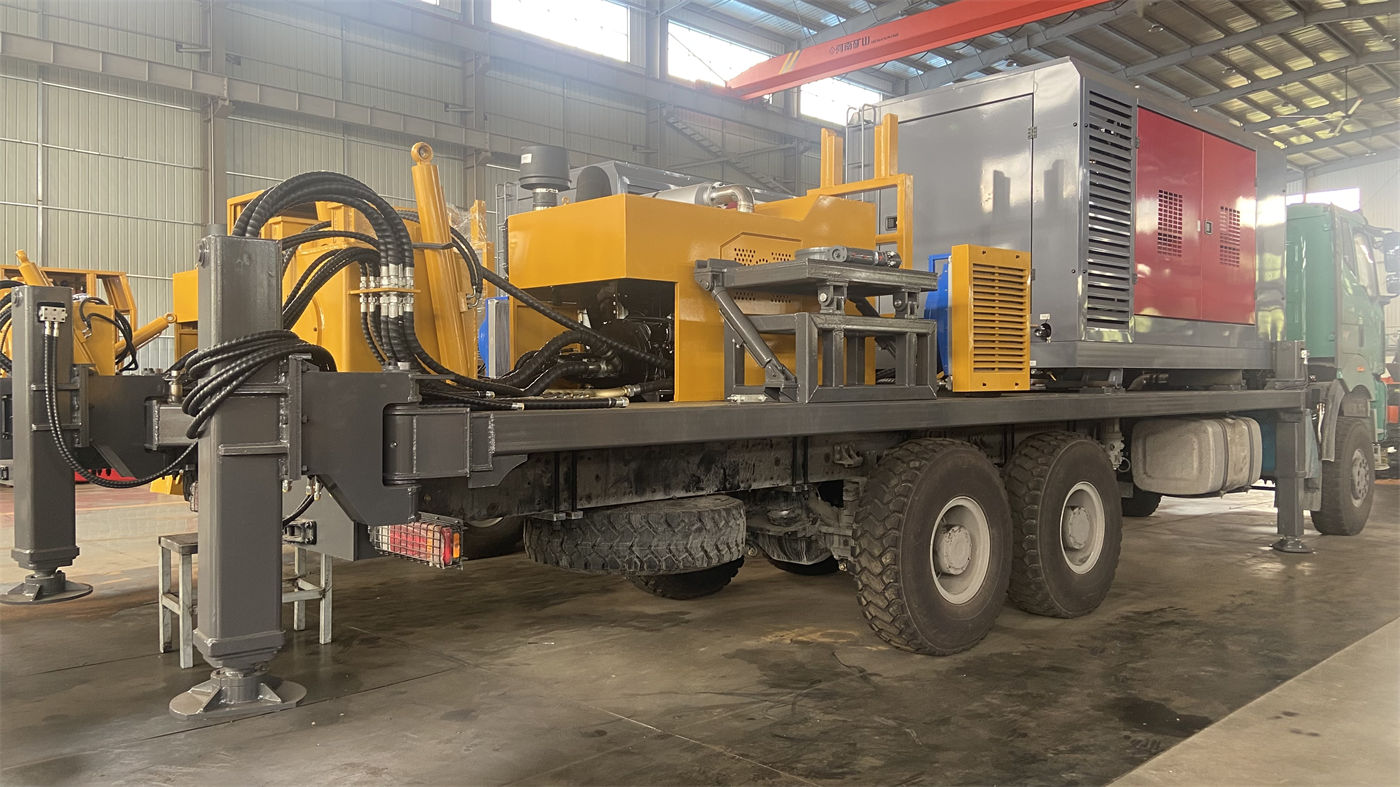
The documentation does not provide a crawler ground pressure value, so it is impossible to infer from it whether a particular gravel layer can support the entire machine. Ground bearing capacity must be verified separately based on site conditions.
Under what premises should the 21° reference angle be used?
The maximum climbing angle reference of 21° is a reference value for an angle limit. The documentation does not list the preconditions for this value item by item. On gravel sites in mining areas, slopes often occur together with other conditions: loose gravel on the slope surface, standing water at the base, and compacted hard crust or floating debris left by haul trucks on the ramp. Under these conditions, the slope that can actually be traversed stably is usually lower than on dry, uniform slopes.
Therefore, treating this 21° as the sole starting point for on-site traversability judgment is not reliable. A more practical approach is to list each ramp section the equipment must pass on site individually, record the slope, length, surface condition, and turning room at the top and bottom, and then confirm section by section.
Wet/slippery and loose conditions affect different stages
The documentation lists 'wet/slippery conditions' and 'ground bearing capacity' side by side in the relocation precautions, indicating that they are two independent verification items.
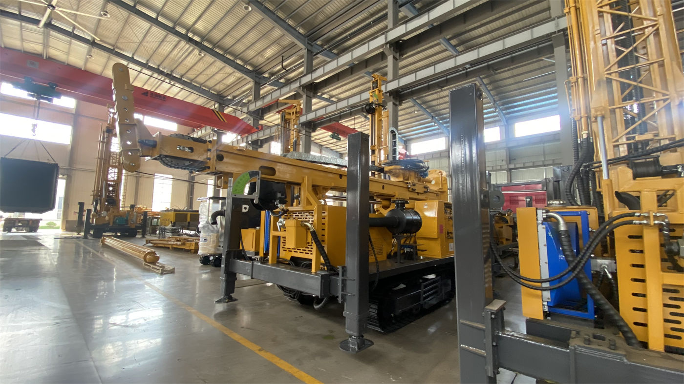
- Wet/slippery mainly affects the adhesion conditions between the crawler and the ground, occurring on ramps, in ponding areas, and on compacted clay surfaces;
- Loose conditions affect the support conditions beneath the crawler, occurring on freshly dumped gravel, spoil bank surfaces, and backfilled areas.
If a route is selected based only on slope, ignoring whether the surface is dry gravel or water-soaked powdery material, the actual traversability of the same slope may be completely different. This judgment must be made on site and cannot be based solely on the parameter table.
Outrigger support and crawler travel are two independent conditions
The WR500S hydraulic outrigger stroke is 1.6 m. The documentation states its purpose is equipment leveling and stable support, and notes that additional pads should be used on soft ground to prevent settlement after prolonged loading of the outriggers. For outrigger support on gravel sites in mining areas, the following points need attention:
- Whether the gravel layer beneath the outriggers will rearrange and cause local subsidence under continuous load;
- Whether the load on the four outriggers is even, and whether one side rests on compacted hard crust while the other rests on newly filled gravel;
- After the outriggers are extended, whether the overall level state of the equipment meets the requirements for mast stress and borehole deviation control in 500-meter-class long-duration construction.
Being able to drive the crawler to the borehole location does not mean the outriggers can provide stable support. These two matters need to be verified separately.
Overall weight and dimensions constrain entry and borehole layout
The overall weight is approximately 10.6 T, and dimensions are approximately 6.52 × 1.85 × 2.51 m. In transport mode, the telescopic mast can reduce the equipment's outer profile, but after arriving on site, space for mast deployment and for handling 6 m drill rods must still be reserved. A common situation on mining sites is ore, pipelines, or temporary facilities stacked beside the borehole, leaving less clear space than expected.
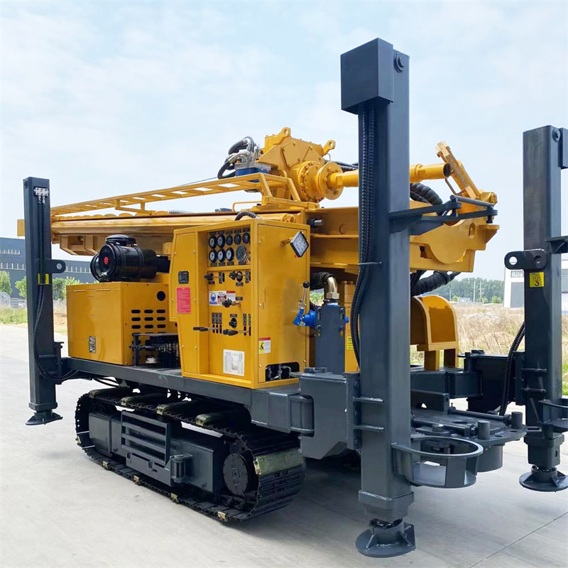
The transport-related verification items listed in the documentation include vehicle load capacity, road width and height limits, telescopic mast locking, equipment securing points, and drill rod bundling status. These are items that must be confirmed one by one before relocation and are separate from the capabilities of the chassis itself.
Items worth checking first on gravel sites
| Verification item | Corresponding documentation information | What cannot be inferred from the documentation |
|---|---|---|
| Travel route between boreholes | Travel speed approximately 3 km/h | Actual length and travel time of the specific route |
| Ramp traversability | Maximum climbing angle reference 21° | Actual achievable slope on wet/slippery and loose surfaces |
| Crawler adhesion conditions | Documentation notes to confirm wet/slippery conditions | On-site surface material and moisture content |
| Outrigger support conditions | Outrigger stroke 1.6 m; pads should be added on soft soil | Settlement of the gravel layer under continuous load |
| Entry transport | Overall weight approximately 10.6 T, dimensions approximately 6.52 × 1.85 × 2.51 m | Width, height, and bearing conditions of internal mining roads |
| Borehole clearance | Telescopic mast and 6 m drill rods | Actual space occupied by on-site stacks and facilities |
Matters requiring separate implementation beyond the documentation
The publicly available WR500S documentation does not provide a crawler ground pressure value, nor does it provide detailed climbing capability data under different ground conditions. Therefore, the traversability of the crawler chassis on gravel sites in mining areas must be confirmed separately for each specific borehole's route, slope, and surface condition. Treating parameters such as travel speed, reference climbing angle, and overall weight as universal admission standards would ignore the differences caused by on-site surface conditions.
When it involves long-term outrigger support, pad installation on soft ground, and arrangements for traversing wet/slippery ramps, the specific methods should be confirmed separately in light of actual on-site conditions; the notes in the documentation cannot replace on-site judgment.